Performance of continuum and shell elements for linear analysis of bending problems | ||
| ||
ProductsAbaqus/StandardAbaqus/Explicit
It is well known that fully integrated linear isoparametric continuum elements, in both two and three dimensions, are too stiff in modeling the simple flexural deformation of a beam. Similarly, fully integrated standard displacement formulations for 4-node shell elements are too stiff in modeling bending about an axis perpendicular to the plane of the shell; i.e., in-plane bending. Full integration refers to the Gauss integration order required for exact integration of the polynomial of the order being integrated when the element is rectangular. Although full-order integration elements can represent rigid-body and constant-strain displacement fields exactly, they tend to “lock” in bending problems because a disproportionately large shear-related strain energy arises, which greatly increases the flexural rigidity of the model.
Problem description
Continuum elements with good bending behavior
In Abaqus there are several alternative continuum elements that can be used to overcome this shear-locking deficiency:
-
Second-order isoparametric elements—these elements can reproduce quadratic displacement fields, thus enabling them to model a pure bending response without any shear strains. They are available only in Abaqus/Standard.
-
Incompatible mode elements—the addition of incompatible modes to the linear isoparametric elements eliminates shear locking and enables these elements to have excellent bending properties.
-
Reduced-integration linear isoparametric elements—reduced integration in the evaluation of the element strain energy eliminates the shear locking phenomenon. These elements are available in both Abaqus/Standard and Abaqus/Explicit. Generally, multiple reduced-integration elements through the thickness are needed to model the bending response accurately. However, the enhanced hourglass control approach in Abaqus/Standard and Abaqus/Explicit can provide good bending behavior even with a coarse mesh. The displacement solutions for linear elastic materials obtained with reduced-integration elements using enhanced hourglass control closely match those obtained with incompatible mode elements since they are both based on the same assumed strain formulation.
-
Continuum shell elements—these elements behave similar to shell elements and, therefore, can be used effectively for modeling slender structures dominated by bending behavior.
Solid isoparametric quadrilaterals and hexahedra and Continuum elements with incompatible modes provide detailed discussions of the element formulations.
Shell elements with good in-plane bending behavior
In many loading situations shell elements undergo substantial bending in the plane of the element. In Abaqus shell element S4 uses an assumed strain treatment for its membrane response that is designed to eliminate parasitic shear stresses that occur when the element is subjected to in-plane bending. In addition, the assumed strain field is designed to eliminate artificial stiffening during in-plane bending due to Poisson's ratio effects. See Finite-strain shell element formulation for a description of the assumed strain treatment in S4 elements. The reduced-integration element, S4R, exhibits good in-plane bending behavior with enhanced hourglass control in both Abaqus/Standard and Abaqus/Explicit.
Incompatible mode elements
The first-order quadrilateral continuum elements of type CPS4I, CPE4I, CAX4I, CPEG4I, and C3D8I, as well as the related hybrid elements, are enhanced by incompatible modes to improve the bending behavior. In addition to the displacement degrees of freedom, incompatible deformation modes are added internally to the elements. The primary effect of these degrees of freedom is to eliminate the parasitic shear stresses that are observed in regular linear continuum elements if they are loaded in bending.
In addition, these degrees of freedom eliminate artificial stiffening in bending due to Poisson's effect. In regular linear continuum elements, the linear variation of the axial stress due to bending is accompanied by a linear variation of the stress perpendicular to the bending direction, which leads to incorrect stresses and an overestimation of the stiffness. The incompatible modes prevent such a stress from occurring.
Continuum element integration schemes
The different numerical integration schemes used by the elements mentioned above in evaluating the stiffness matrices are discussed here. The integration scheme plays a vital role in determining the properties of an element.
-
Linear isoparametric elements use selectively reduced integration. Selectively reduced integration is used in Abaqus for linear plane strain, generalized plane strain, axisymmetric, and three-dimensional isoparametric elements. In these elements second-order Gaussian integration is used for the deviatoric strains, with one point used to integrate volumetric strain terms, to avoid excessive constraint when the element's response is essentially incompressible.
-
Second-order isoparametric elements use full or reduced integration. The full and reduced-integration schemes use third- and second-order Gaussian integration schemes, respectively.
-
Incompatible mode elements use full integration. The use of full Gaussian quadrature (second-order) requires 2 × 2 integration points in two dimensions (e.g., CPS4I) and 2 × 2 × 2 points in three dimensions (e.g., C3D8I).
-
Reduced-integration, linear isoparametric elements use uniformly reduced integration. The integration scheme is based on the “uniform strain formulation,” where an average strain is calculated over the element volume. Uniformly reduced-integration rules are appealing computationally because a substantial reduction in the number of function evaluations is achieved.
Hourglass control for reduced-integration elements
Reduced integration has a serious drawback: it can result in a mesh instability, commonly referred to as “hourglassing.” Kinematic zero-energy modes are present in reduced-integration element formulations so that, if the mesh is geometrically consistent with a global pattern of such modes, a singular stiffness matrix is obtained and the element is rendered ineffective.
Flanagan and Belytschko (1981) and Belytschko et al. (1984) describe a control technique to deal with the hourglassing of first-order uniform-strain elements. The method involves the construction of generalized hourglass strains that are orthogonal to the rigid body modes. Typically, hourglass stresses are related to the hourglass strains through artificial stiffness parameters. These stiffness coefficients are relatively small when compared to the actual stiffness of the material. The Introduction: general describes the artificial stiffness values used by default if they are not specified. The enhanced hourglass controls available in Abaqus uses stiffness coefficients based on the enhanced assumed strain method. It gives good displacement solutions for linear elastic materials and provides increased resistance to hourglassing for nonlinear materials. Element types CPS4R, CPE4R, CPEG4R, CAX4R, C3D8R, and the corresponding hybrid elements are based on this approach. Shell element types S4R and S4R5 are based on similar concepts. For modified tetrahedral and triangular elements the total stiffness approach is specified.
![]()
Geometry and models
Three examples are considered here to illustrate the behavior of the various elements in modeling bending behavior.
The same number of first- and second-order elements is used for each mesh layout. Obviously, for an equal number of elements, the mesh for the second-order elements will contain more nodes and, thus, have a larger number of degrees of freedom. However, the objective is to show that, even with fewer degrees of freedom, the incompatible mode elements and—to a certain extent—the reduced-integration, linear elements give comparably accurate results with respect to the second-order elements. Hence, the meshes included here are coarse and should not be taken as good modeling practice.
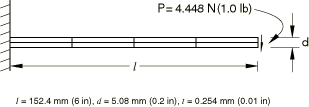
Cantilever beam with end shear load
The first example is the linear static analysis of a cantilever with an end shear load. The geometry is shown in Figure 1. The Young's modulus is 689.5 GPa (10 × 107 lb/in2), and Poisson's ratio is 0. In Abaqus/Standard and Abaqus/Explicit the following four meshes are used: 1, 2, 4, or 8 elements through the depth of the beam, combined with 4 or 16 elements along the beam. The 8 × 16 mesh is included to examine the “converged” solution. The resulting end deflections are normalized with respect to the Euler-Bernoulli beam theory prediction of 2.74 mm (0.108 in) and tabulated in Table 1. Although this example is a beam problem, the thickness is chosen to be small so that the problem can be reasonably modeled with both continuum and shell elements. Due to the small thickness, warning messages may be issued for poor aspect ratios for analyses involving coarser meshes of three-dimensional continuum elements. The analytical solution depends only on the thickness through the combination Young's modulus times thickness (). Hence, any thickness can be used so long as the product remains fixed; the solution remains the same with the exception of the tetrahedral elements, where the thickness influences the tetrahedral quality measure and, hence, the displacement solution.
In the Abaqus/Explicit analyses the load is applied to the structure using a SMOOTH STEP amplitude curve to minimize the dynamic effects.
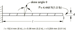
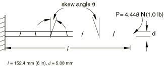
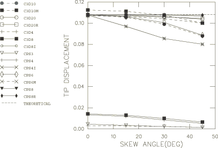
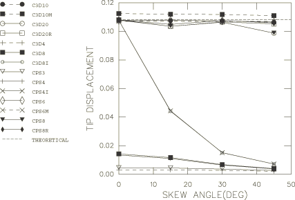
Skew sensitivity analysis of cantilever beam
The second example examines the skew sensitivity of the elements with respect to two shapes: parallelogram and trapezoidal. The cantilever beam and loading are the same as in the first example. A 1 × 8 mesh is used for both shapes when the elements are quadrilateral or hexahedral, as shown in Figure 2 and Figure 3. When the problem is modeled using triangular or tetrahedral elements, the basic parallelogram or trapezoidal shape meshed with one quadrilateral or hexahedral element is filled with either two triangular elements in the two-dimensional case or five tetrahedral elements in the three-dimensional case. Therefore, the triangular and tetrahedral elements do not have a true parallelogram or trapezoidal shape. The following skew angles are tested for the Abaqus/Standard and Abaqus/Explicit runs: 0°, 15°, 30°, and 45°. The resulting end deflections are again normalized with respect to the Euler-Bernoulli beam theory prediction of 2.74 mm (0.108 in) and tabulated in Table 2 and Table 3. The use of a single layer of elements precludes the testing of the reduced-integration linear isoparametric elements (except when using enhanced hourglass control) since a minimum of four layers is required for acceptable results.
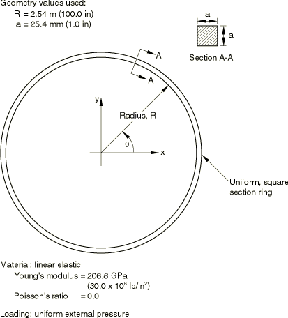
Buckling analysis of ring under external pressure
The final example is the buckling analysis of a ring in a plane under external pressure. The geometry and material are the same as those used in Buckling of a ring in a plane under external pressure and are shown in Figure 4. The ring buckling problem requires a rather fine mesh in the circumferential direction, presumably to model the strain gradients accurately in the buckling mode. Using symmetry boundary conditions, only a 45° sector of the ring is modeled, which is enough to reproduce the primary buckling mode. Table 5 gives the solutions obtained with various models for this case. The exact solution, based on Euler-Bernoulli beam theory, is a critical buckling pressure of 51.71 KPa (7.5 lb/in2).
![]()
Results and discussion
The results for each analysis are described below.
Cantilever beam with end shear load
As expected, the second-order elements in Abaqus/Standard give excellent results even with the coarse 1 × 4 mesh, with the reduced-integration CPS8R and C3D20R elements giving the most accurate results. The regular second-order and the modified triangular and tetrahedral elements also exhibit excellent behavior in bending. The incompatible mode elements in Abaqus/Standard (CPS4I and C3D8I) and the reduced-integration elements in Abaqus/Standard and Abaqus/Explicit (C3D8R, CPS4R, and S4R) with enhanced hourglass control perform just as well as the second-order elements, indicating their excellent bending properties when they are used as rectangles and lined up with the principal axes of bending. The results for the one-layer 1 × 4 mesh are already very good. Increasing the number of layers does not improve the results. However, more layers are required for accurate analysis when material nonlinearities are present. The assumed strain shell element S4 performs relatively well given the coarseness of the mesh and the fact that S4 does not have internal degrees of freedom like CPS4I and C3D8I. With mesh refinement the solution improves.
On the other hand, the linear isoparametric elements exhibit extremely stiff bending behavior, far too stiff for practical applications. Even with the very fine 8 × 16 mesh, the displacement is still less than half of the correct value. In a critical analysis of an exactly integrated plane stress element, Prathap (1985) points out that “improvement of the idealization by increasing the number of elements through the depth does not relieve the parasitic shear locking [i.e., excessively stiff behavior in bending situations].” This observation is confirmed by the results with element types CPS3, CPS4, C3D4, and C3D8 in this example.
The reduced-integration linear elements CPS4R, C3D8R, S4R, and SC8R converge rapidly as the mesh is refined. However, the convergence to the correct result is no longer monotonic. This is an effect of the under-integration of the element stiffness: there is no guarantee of an upper bound to the stiffness of the solution, and the response may fall on the soft side. With reduced integration the number of elements through the depth plays a critical role. Two elements through the depth fail to provide engineering accuracy. Four elements through the depth, with four elements along the length, provide acceptable results. If the idealization involved only one element through the depth, the material integration points would all lie on the neutral axis, and the bending behavior would depend entirely on the (artificial) hourglass stiffness. Combined with enhanced hourglass control, the CPS4R, C3D8R, and S4R elements provide excellent results even with the coarse 1 × 4 mesh. The results closely match those obtained with incompatible mode elements in Abaqus/Standard since both analyses are based on the same assumed strain formulation.
Skew sensitivity analysis of cantilever beam
Figure 5 and Figure 6 show the effect of skewing the elements into parallelograms and trapezoids. We see that the second-order elements do not show strong sensitivity to such distortion, while the incompatible mode elements and element S4 show more sensitivity, especially to trapezoidal distortion, which quickly causes them to be impractically stiff. Both the regular second-order and modified triangular/tetrahedral elements show less sensitivity to the trapezoidal skew than the second-order quadrilateral/hexahedral elements, but they show more sensitivity than the rectangular elements in the parallelogram skew test. The Abaqus/Explicit results and the linear reduced-integration elements in Abaqus/Standard with enhanced hourglass control closely match the results obtained with incompatible mode elements in Abaqus/Standard.
Table 2 and Table 3 summarize the effect of skewing continuum, shell, and continuum shell elements into parallelograms and trapezoids. The skewing is done in the element in-plane direction for the shell and continuum shell models. Table 4 summarizes the effect of skewing the continuum shell element SC8R in the thickness direction of the element. The results indicate that the behavior is insensitive to mesh distortion that occurs in the thickness direction.
Buckling analysis of ring under external pressure
Both the incompatible mode and second-order elements give excellent results, even with the coarse mesh. The linear reduced-integration elements with hourglass control based on total stiffness give acceptable results that again hover about the correct value: higher for the coarse mesh and lower for the fine mesh. The linear reduced-integration elements with enhanced hourglass control give results that closely match the results obtained with incompatible mode elements. As expected, the linear full-integration elements once again give extremely stiff results: between 8 to 93 times the actual buckling pressure.
![]()
Additional modeling considerations
These analyses illustrate the use of continuum elements to simulate bending behavior of thin structures. Similarly, these analyses illustrate the use of shell element S4 for bending in the plane of the element. In general, the use of beam or shell elements (with out-of-plane bending) is recommended for thin structures; the difficulties discussed here would be encountered only if the analyst could not use the more appropriate bending elements for some reason. The results presented here do not reflect the usefulness or importance of continuum elements in other types of problems.
We have seen that the incompatible mode elements perform almost as well as the second-order elements in many situations if the elements have an approximately rectangular shape. The performance is considerably poorer if the elements have a parallelogram shape and quickly becomes unacceptable with trapezoidal element shapes. In addition, these elements offer no advantages when a side is degenerated or collapsed into a node. The degenerated elements can only represent a constant strain field, and the incompatible modes cannot improve on such fields.
Due to the internal degrees of freedom (4 for CPS4I; 5 for CPE4I, CAX4I, and CPEG4I; and 13 for C3D8I) the incompatible mode elements are somewhat more expensive than regular displacement elements but are more economical than the second-order elements. The additional degrees of freedom do not increase the wavefront size substantially, since they can be eliminated immediately. In addition, it is not necessary to use selectively reduced integration, which partially offsets the cost of the additional degrees of freedom.
The reduced-integration, linear elements also give satisfactory solutions for the set of problems attempted here when a minimum of four layers is used. However, there are cases where the elements may yield a nearly singular stiffness and, hence, physically unreasonable solutions. This is especially true when large-strain problems are analyzed. Thus, as with all modeling decisions, analysts must develop their discretization with careful testing of the effectiveness of the elements for a particular application.
![]()
Further examples
The use of the elements discussed above is illustrated further in the following example problems:
![]()
Input files
- linbending_typ_cant.inp
-
Typical input data for the cantilever analysis.
- linbending_typ_paral.inp
-
Typical input data for the skew sensitivity analysis of parallelogram-shaped elements.
- linbending_typ_trap.inp
-
Typical input data for the skew sensitivity analysis of trapezoidal-shaped elements.
- linbending_typ_ring.inp
-
Typical input data for the ring buckling problem.
Abaqus/Standard input files:
Cantilever analysisC3D4 elements:- linbending_c3d4_cant_1x4.inp
-
1 × 4 mesh.
- linbending_c3d4_cant_2x4.inp
-
2 × 4 mesh.
- linbending_c3d4_cant_4x4.inp
-
4 × 4 mesh.
- linbending_c3d4_cant_8x16.inp
-
8 × 16 mesh.
- linbending_c3d8_cant_1x4.inp
-
1 × 4 mesh.
- linbending_c3d8_cant_2x4.inp
-
2 × 4 mesh.
- linbending_c3d8_cant_4x4.inp
-
4 × 4 mesh.
- linbending_c3d8_cant_8x16.inp
-
8 × 16 mesh.
- linbending_c3d8i_cant_1x4.inp
-
1 × 4 mesh.
- linbending_c3d8i_cant_2x4.inp
-
2 × 4 mesh.
- linbending_c3d8i_cant_4x4.inp
-
4 × 4 mesh.
- linbending_c3d8i_cant_8x16.inp
-
8 × 16 mesh.
- linbending_c3d8r_cant_2x4.inp
-
2 × 4 mesh.
- linbending_c3d8r_cant_4x4.inp
-
4 × 4 mesh.
- linbending_c3d8r_cant_8x16.inp
-
8 × 16 mesh.
- linbending_c3d8r_cant_1x4_eh.inp
-
1 × 4 mesh.
- linbending_c3d8r_cant_2x4_eh.inp
-
2 × 4 mesh.
- linbending_c3d8r_cant_4x4_eh.inp
-
4 × 4 mesh.
- linbending_c3d8r_cant_8x16_eh.inp
-
8 × 16 mesh.
- linbending_c3d10_cant_1x4.inp
-
1 × 4 mesh.
- linbending_c3d10_cant_2x4.inp
-
2 × 4 mesh.
- linbending_c3d10_cant_4x4.inp
-
4 × 4 mesh.
- linbending_c3d10_cant_8x16.inp
-
8 × 16 mesh.
- linbending_c3d10hs_cant_1x4.inp
-
1 × 4 mesh.
- linbending_c3d10hs_cant_2x4.inp
-
2 × 4 mesh.
- linbending_c3d10hs_cant_4x4.inp
-
4 × 4 mesh.
- linbending_c3d10hs_cant_8x16.inp
-
8 × 16 mesh.
- linbending_c3d10_mcant_1x4.inp
-
1 × 4 mesh.
- linbending_c3d10_mcant_2x4.inp
-
2 × 4 mesh.
- linbending_c3d10_mcant_4x4.inp
-
4 × 4 mesh.
- linbending_c3d10_mcant_8x16.inp
-
8 × 16 mesh.
- linbending_c3d20_cant_1x4.inp
-
1 × 4 mesh.
- linbending_c3d20_cant_2x4.inp
-
2 × 4 mesh.
- linbending_c3d20_cant_4x4.inp
-
4 × 4 mesh.
- linbending_c3d20_cant_8x16.inp
-
8 × 16 mesh.
- linbending_c3d20r_cant_1x4.inp
-
1 × 4 mesh.
- linbending_c3d20r_cant_2x4.inp
-
2 × 4 mesh.
- linbending_c3d20r_cant_4x4.inp
-
4 × 4 mesh.
- linbending_c3d20r_cant_8x16.inp
-
8 × 16 mesh.
- linbending_cps3_cant_1x4.inp
-
1 × 4 mesh.
- linbending_cps3_cant_2x2.inp
-
2 × 2 mesh.
- linbending_cps3_cant_4x4.inp
-
4 × 4 mesh.
- linbending_cps3_cant_8x16.inp
-
8 × 16 mesh.
- linbending_cps4_cant_1x4.inp
-
1 × 4 mesh.
- linbending_cps4_cant_2x4.inp
-
2 × 4 mesh.
- linbending_cps4_cant_4x4.inp
-
4 × 4 mesh.
- linbending_cps4_cant_8x16.inp
-
8 × 16 mesh.
- linbending_cps4i_cant_1x4.inp
-
1 × 4 mesh.
- linbending_cps4i_cant_2x4.inp
-
2 × 4 mesh.
- linbending_cps4i_cant_4x4.inp
-
4 × 4 mesh.
- linbending_cps4i_cant_8x16.inp
-
8 × 16 mesh.
- linbending_cps4r_cant_2x4.inp
-
2 × 4 mesh.
- linbending_cps4r_cant_4x4.inp
-
4 × 4 mesh.
- linbending_cps4r_cant_8x16.inp
-
8 × 16 mesh.
- linbending_cps4r_cant_1x4_eh.inp
-
1 × 4 mesh.
- linbending_cps4r_cant_2x4_eh.inp
-
2 × 4 mesh.
- linbending_cps4r_cant_4x4_eh.inp
-
4 × 4 mesh.
- linbending_cps4r_cant_8x16_eh.inp
-
8 × 16 mesh.
- linbending_cps6_cant_1x4.inp
-
1 × 4 mesh.
- linbending_cps6_cant_2x4.inp
-
2 × 4 mesh.
- linbending_cps6_cant_4x4.inp
-
4 × 4 mesh.
- linbending_cps6_cant_8x16.inp
-
8 × 16 mesh.
- linbending_cps6m_cant_1x4.inp
-
1 × 4 mesh.
- linbending_cps6m_cant_2x4.inp
-
2 × 4 mesh.
- linbending_cps6m_cant_4x4.inp
-
4 × 4 mesh.
- linbending_cps6m_cant_8x16.inp
-
8 × 16 mesh.
- linbending_cps8_cant_1x4.inp
-
1 × 4 mesh.
- linbending_cps8_cant_2x4.inp
-
2 × 4 mesh.
- linbending_cps8_cant_4x4.inp
-
4 × 4 mesh.
- linbending_cps8_cant_8x16.inp
-
8 × 16 mesh.
- linbending_cps8r_cant_1x4.inp
-
1 × 4 mesh.
- linbending_cps8r_cant_2x4.inp
-
2 × 4 mesh.
- linbending_cps8r_cant_4x4.inp
-
4 × 4 mesh.
- linbending_cps8r_cant_8x16.inp
-
8 × 16 mesh.
- linbending_css8_cant_1x4.inp
-
1 × 4 mesh.
- linbending_css8_cant_2x4.inp
-
2 × 4 mesh.
- linbending_css8_cant_4x4.inp
-
4 × 4 mesh.
- linbending_css8_cant_8x16.inp
-
8 × 16 mesh.
- linbending_s4_cant_1x4.inp
-
1 × 4 mesh.
- linbending_s4_cant_2x4.inp
-
2 × 4 mesh.
- linbending_s4_cant_4x4.inp
-
4 × 4 mesh.
- linbending_s4_cant_8x16.inp
-
8 × 16 mesh.
- linbending_s4r_cant_1x4_eh.inp
-
1 × 4 mesh.
- linbending_s4r_cant_2x4_eh.inp
-
2 × 4 mesh.
- linbending_s4r_cant_4x4_eh.inp
-
4 × 4 mesh.
- linbending_s4r_cant_8x16_eh.inp
-
8 × 16 mesh.
- linbending_c3d4_1x8_ang0.inp
-
1 × 8 mesh; skew angle of 0°.
- linbending_c3d4_paral_ang15.inp
-
Parallelogram shape; skew angle of 15°.
- linbending_c3d4_paral_ang30.inp
-
Parallelogram shape; skew angle of 30°.
- linbending_c3d4_paral_ang45.inp
-
Parallelogram shape; skew angle of 45°.
- linbending_c3d4_trap_ang15.inp
-
Trapezoidal shape; skew angle of 15°.
- linbending_c3d4_trap_ang30.inp
-
Trapezoidal shape; skew angle of 30°.
- linbending_c3d4_trap_ang45.inp
-
Trapezoidal shape; skew angle of 45°.
- linbending_c3d8_1x8_ang0.inp
-
1 × 8 mesh; skew angle of 0°.
- linbending_c3d8_paral_ang15.inp
-
Parallelogram shape; skew angle of 15°.
- linbending_c3d8_paral_ang30.inp
-
Parallelogram shape; skew angle of 30°.
- linbending_c3d8_paral_ang45.inp
-
Parallelogram shape; skew angle of 45°.
- linbending_c3d8_trap_ang15.inp
-
Trapezoidal shape; skew angle of 15°.
- linbending_c3d8_trap_ang30.inp
-
Trapezoidal shape; skew angle of 30°.
- linbending_c3d8_trap_ang45.inp
-
Trapezoidal shape; skew angle of 45°.
- linbending_c3d8i_1x8_ang0.inp
-
1 × 8 mesh; skew angle of 0°.
- linbending_c3d8i_paral_ang15.inp
-
Parallelogram shape; skew angle of 15°.
- linbending_c3d8i_paral_ang30.inp
-
Parallelogram shape; skew angle of 30°.
- linbending_c3d8i_paral_ang45.inp
-
Parallelogram shape; skew angle of 45°.
- linbending_c3d8i_trap_ang15.inp
-
Trapezoidal shape; skew angle of 15°.
- linbending_c3d8i_trap_ang30.inp
-
Trapezoidal shape; skew angle of 30°.
- linbending_c3d8i_trap_ang45.inp
-
Trapezoidal shape; skew angle of 45°.
- linbending_c3d8r_1x8_ang0_eh.inp
-
1 × 8 mesh; skew angle of 0°.
- linbending_c3d8r_paral_ang15_eh.inp
-
Parallelogram shape; skew angle of 15°.
- linbending_c3d8r_paral_ang30_eh.inp
-
Parallelogram shape; skew angle of 30°.
- linbending_c3d8r_paral_ang45_eh.inp
-
Parallelogram shape; skew angle of 45°.
- linbending_c3d8r_trap_ang15_eh.inp
-
Trapezoidal shape; skew angle of 15°.
- linbending_c3d8r_trap_ang30_eh.inp
-
Trapezoidal shape; skew angle of 30°.
- linbending_c3d8r_trap_ang45_eh.inp
-
Trapezoidal shape; skew angle of 45°.
- linbending_c3d10_1x8_ang0.inp
-
1 × 8 mesh; skew angle of 0°.
- linbending_c3d10_paral_ang15.inp
-
Parallelogram shape; skew angle of 15°.
- linbending_c3d10_paral_ang30.inp
-
Parallelogram shape; skew angle of 30°.
- linbending_c3d10_paral_ang45.inp
-
Parallelogram shape; skew angle of 45°.
- linbending_c3d10_trap_ang15.inp
-
Trapezoidal shape; skew angle of 15°.
- linbending_c3d10_trap_ang30.inp
-
Trapezoidal shape; skew angle of 30°.
- linbending_c3d10_trap_ang45.inp
-
Trapezoidal shape; skew angle of 45°.
- linbending_c3d10hs_1x8_ang0.inp
-
1 × 8 mesh; skew angle of 0°.
- linbending_c3d10hs_paral_ang15.inp
-
Parallelogram shape; skew angle of 15°.
- linbending_c3d10hs_paral_ang30.inp
-
Parallelogram shape; skew angle of 30°.
- linbending_c3d10hs_paral_ang45.inp
-
Parallelogram shape; skew angle of 45°.
- linbending_c3d10hs_trap_ang15.inp
-
Trapezoidal shape; skew angle of 15°.
- linbending_c3d10hs_trap_ang30.inp
-
Trapezoidal shape; skew angle of 30°.
- linbending_c3d10hs_trap_ang45.inp
-
Trapezoidal shape; skew angle of 45°.
- linbending_c3d10m_1x8_ang0.inp
-
1 × 8 mesh; skew angle of 0°.
- linbending_c3d10m_paral_ang15.inp
-
Parallelogram shape; skew angle of 15°.
- linbending_c3d10m_paral_ang30.inp
-
Parallelogram shape; skew angle of 30°.
- linbending_c3d10m_paral_ang45.inp
-
Parallelogram shape; skew angle of 45°.
- linbending_c3d10m_trap_ang15.inp
-
Trapezoidal shape; skew angle of 15°.
- linbending_c3d10m_trap_ang30.inp
-
Trapezoidal shape; skew angle of 30°.
- linbending_c3d10m_trap_ang45.inp
-
Trapezoidal shape; skew angle of 45°.
- linbending_c3d20_1x8_ang0.inp
-
1 × 8 mesh; skew angle of 0°.
- linbending_c3d20_paral_ang15.inp
-
Parallelogram shape; skew angle of 15°.
- linbending_c3d20_paral_ang30.inp
-
Parallelogram shape; skew angle of 30°.
- linbending_c3d20_paral_ang45.inp
-
Parallelogram shape; skew angle of 45°.
- linbending_c3d20_trap_ang15.inp
-
Trapezoidal shape; skew angle of 15°.
- linbending_c3d20_trap_ang30.inp
-
Trapezoidal shape; skew angle of 30°.
- linbending_c3d20_trap_ang45.inp
-
Trapezoidal shape; skew angle of 45°.
- linbending_c3d20r_1x8_ang0.inp
-
1 × 8 mesh; skew angle of 0°.
- linbending_c3d20r_paral_ang15.inp
-
Parallelogram shape; skew angle of 15°.
- linbending_c3d20r_paral_ang30.inp
-
Parallelogram shape; skew angle of 30°.
- linbending_c3d20r_paral_ang45.inp
-
Parallelogram shape; skew angle of 45°.
- linbending_c3d20r_trap_ang15.inp
-
Trapezoidal shape; skew angle of 15°.
- linbending_c3d20r_trap_ang30.inp
-
Trapezoidal shape; skew angle of 30°.
- linbending_c3d20r_trap_ang45.inp
-
Trapezoidal shape; skew angle of 45°.
- linbending_cps3_1x8_ang0.inp
-
1 × 8 mesh; skew angle of 0°.
- linbending_cps3_paral_ang15.inp
-
Parallelogram shape; skew angle of 15°.
- linbending_cps3_paral_ang30.inp
-
Parallelogram shape; skew angle of 30°.
- linbending_cps3_paral_ang45.inp
-
Parallelogram shape; skew angle of 45°.
- linbending_cps3_trap_ang15.inp
-
Trapezoidal shape; skew angle of 15°.
- linbending_cps3_trap_ang30.inp
-
Trapezoidal shape; skew angle of 30°.
- linbending_cps3_trap_ang45.inp
-
Trapezoidal shape; skew angle of 45°.
- linbending_cps4_1x8_ang0.inp
-
1 × 8 mesh; skew angle of 0°.
- linbending_cps4_paral_ang15.inp
-
Parallelogram shape; skew angle of 15°.
- linbending_cps4_paral_ang30.inp
-
Parallelogram shape; skew angle of 30°.
- linbending_cps4_paral_ang45.inp
-
Parallelogram shape; skew angle of 45°.
- linbending_cps4_trap_ang15.inp
-
Trapezoidal shape; skew angle of 15°.
- linbending_cps4_trap_ang30.inp
-
Trapezoidal shape; skew angle of 30°.
- linbending_cps4_trap_ang45.inp
-
Trapezoidal shape; skew angle of 45°.
- linbending_cps4i_mesh18_ang0.inp
-
1 × 8 mesh; skew angle of 0°.
- linbending_cps4i_paral_ang15.inp
-
Parallelogram shape; skew angle of 15°.
- linbending_cps4i_paral_ang30.inp
-
Parallelogram shape; skew angle of 30°.
- linbending_cps4i_paral_ang45.inp
-
Parallelogram shape; skew angle of 45°.
- linbending_cps4i_trap_ang15.inp
-
Trapezoidal shape; skew angle of 15°.
- linbending_cps4i_trap_ang30.inp
-
Trapezoidal shape; skew angle of 30°.
- linbending_cps4i_trap_ang45.inp
-
Trapezoidal shape; skew angle of 45°.
- linbending_cps4r_1x8_ang0_eh.inp
-
1 × 8 mesh; skew angle of 0°.
- linbending_cps4r_paral_ang15_eh.inp
-
Parallelogram shape; skew angle of 15°.
- linbending_cps4r_paral_ang30_eh.inp
-
Parallelogram shape; skew angle of 30°.
- linbending_cps4r_paral_ang45_eh.inp
-
Parallelogram shape; skew angle of 45°.
- linbending_cps4r_trap_ang15_eh.inp
-
Trapezoidal shape; skew angle of 15°.
- linbending_cps4r_trap_ang30_eh.inp
-
Trapezoidal shape; skew angle of 30°.
- linbending_cps4r_trap_ang45_eh.inp
-
Trapezoidal shape; skew angle of 45°.
- linbending_cps6_1x8_ang0.inp
-
1 × 8 mesh; skew angle of 0°.
- linbending_cps6_paral_ang15.inp
-
Parallelogram shape; skew angle of 15°.
- linbending_cps6_paral_ang30.inp
-
Parallelogram shape; skew angle of 30°.
- linbending_cps6_paral_ang45.inp
-
Parallelogram shape; skew angle of 45°.
- linbending_cps6_trap_ang15.inp
-
Trapezoidal shape; skew angle of 15°.
- linbending_cps6_trap_ang30.inp
-
Trapezoidal shape; skew angle of 30°.
- linbending_cps6_trap_ang45.inp
-
Trapezoidal shape; skew angle of 45°.
- linbending_cps6m_1x8_ang0.inp
-
1 × 8 mesh; skew angle of 0°.
- linbending_cps6m_paral_ang15.inp
-
Parallelogram shape; skew angle of 15°.
- linbending_cps6m_paral_ang30.inp
-
Parallelogram shape; skew angle of 30°.
- linbending_cps6m_paral_ang45.inp
-
Parallelogram shape; skew angle of 45°.
- linbending_cps6m_trap_ang15.inp
-
Trapezoidal shape; skew angle of 15°.
- linbending_cps6m_trap_ang30.inp
-
Trapezoidal shape; skew angle of 30°.
- linbending_cps6m_trap_ang45.inp
-
Trapezoidal shape; skew angle of 45°.
- linbending_cps8_1x8_ang0.inp
-
1 × 8 mesh; skew angle of 0°.
- linbending_cps8_paral_ang15.inp
-
Parallelogram shape; skew angle of 15°.
- linbending_cps8_paral_ang30.inp
-
Parallelogram shape; skew angle of 30°.
- linbending_cps8_paral_ang45.inp
-
Parallelogram shape; skew angle of 45°.
- linbending_cps8_trap_ang15.inp
-
Trapezoidal shape; skew angle of 15°.
- linbending_cps8_trap_ang30.inp
-
Trapezoidal shape; skew angle of 30°.
- linbending_cps8_trap_ang45.inp
-
Trapezoidal shape; skew angle of 45°.
- linbending_cps8r_1x8_ang0.inp
-
1 × 8 mesh; skew angle of 0°.
- linbending_cps8r_paral_ang15.inp
-
Parallelogram shape; skew angle of 15°.
- linbending_cps8r_paral_ang30.inp
-
Parallelogram shape; skew angle of 30°.
- linbending_cps8r_paral_ang45.inp
-
Parallelogram shape; skew angle of 45°.
- linbending_cps8r_trap_ang15.inp
-
Trapezoidal shape; skew angle of 15°.
- linbending_cps8r_trap_ang30.inp
-
Trapezoidal shape; skew angle of 30°.
- linbending_cps8r_trap_ang45.inp
-
Trapezoidal shape; skew angle of 45°.
- linbending_css8_1x8_ang0.inp
-
1 × 8 mesh; skew angle of 0°.
- linbending_css8_paral_ang15.inp
-
Parallelogram shape; skew angle of 15°.
- linbending_css8_paral_ang30.inp
-
Parallelogram shape; skew angle of 30°.
- linbending_css8_paral_ang45.inp
-
Parallelogram shape; skew angle of 45°.
- linbending_css8_trap_ang15.inp
-
Trapezoidal shape; skew angle of 15°.
- linbending_css8_trap_ang30.inp
-
Trapezoidal shape; skew angle of 30°.
- linbending_css8_trap_ang45.inp
-
Trapezoidal shape; skew angle of 45°.
- linbending_s4_1x8_ang0.inp
-
1 × 8 mesh; skew angle of 0°.
- linbending_s4_paral_ang15.inp
-
Parallelogram shape; skew angle of 15°.
- linbending_s4_paral_ang30.inp
-
Parallelogram shape; skew angle of 30°.
- linbending_s4_paral_ang45.inp
-
Parallelogram shape; skew angle of 45°.
- linbending_s4_trap_ang15.inp
-
Trapezoidal shape; skew angle of 15°.
- linbending_s4_trap_ang30.inp
-
Trapezoidal shape; skew angle of 30°.
- linbending_s4_trap_ang45.inp
-
Trapezoidal shape; skew angle of 45°.
- linbending_s4r_1x8_ang0_eh.inp
-
1 × 8 mesh; skew angle of 0°.
- linbending_s4r_paral_ang15_eh.inp
-
Parallelogram shape; skew angle of 15°.
- linbending_s4r_paral_ang30_eh.inp
-
Parallelogram shape; skew angle of 30°.
- linbending_s4r_paral_ang45_eh.inp
-
Parallelogram shape; skew angle of 45°.
- linbending_s4r_trap_ang15_eh.inp
-
Trapezoidal shape; skew angle of 15°.
- linbending_s4r_trap_ang30_eh.inp
-
Trapezoidal shape; skew angle of 30°.
- linbending_s4r_trap_ang45_eh.inp
-
Trapezoidal shape; skew angle of 45°.
- linbending_sc8r_1x8_ang0_eh.inp
-
1 × 8 mesh; skew angle of 0°.
- linbending_sc8r_paral_ang15_eh.inp
-
Parallelogram shape; skew angle of 15°.
- linbending_sc8r_paral_ang30_eh.inp
-
Parallelogram shape; skew angle of 30°.
- linbending_sc8r_paral_ang45_eh.inp
-
Parallelogram shape; skew angle of 45°.
- linbending_sc8r_trap_ang15_eh.inp
-
Trapezoidal shape; skew angle of 15°.
- linbending_sc8r_trap_ang30_eh.inp
-
Trapezoidal shape; skew angle of 30°.
- linbending_sc8r_trap_ang45_eh.inp
-
Trapezoidal shape; skew angle of 45°.
- linbending_sc8r_1x8_ang0_thk.inp
-
1 × 8 mesh; skew angle of 0° in element thickness direction.
- linbending_sc8r_paral_ang15_thk.inp
-
Parallelogram shape; skew angle of 15° in element thickness direction.
- linbending_sc8r_paral_ang30_thk.inp
-
Parallelogram shape; skew angle of 30° in element thickness direction.
- linbending_sc8r_paral_ang45_thk.inp
-
Parallelogram shape; skew angle of 45° in element thickness direction.
- linbending_sc8r_trap_ang15_thk.inp
-
Trapezoidal shape; skew angle of 15° in element thickness direction.
- linbending_sc8r_trap_ang30_thk.inp
-
Trapezoidal shape; skew angle of 30° in element thickness direction.
- linbending_sc8r_trap_ang45_thk.inp
-
Trapezoidal shape; skew angle of 45° in element thickness direction.
- linbending_ring_c3d4_4x10.inp
-
4 × 10 mesh.
- linbending_ring_c3d4_4x20.inp
-
4 × 20 mesh.
- linbending_ring_c3d8_4x10.inp
-
4 × 10 mesh.
- linbending_ring_c3d8_4x20.inp
-
4 × 20 mesh.
- linbending_ring_c3d8i_4x10.inp
-
4 × 10 mesh.
- linbending_ring_c3d8i_4x20.inp
-
4 × 20 mesh.
- linbending_ring_c3d8r_4x10.inp
-
4 × 10 mesh.
- linbending_ring_c3d8r_4x20.inp
-
4 × 20 mesh.
- linbending_ring_c3d8r_4x10_eh.inp
-
4 × 10 mesh.
- linbending_ring_c3d8r_4x20_eh.inp
-
4 × 20 mesh.
- linbending_ring_c3d10_4x10.inp
-
4 × 10 mesh.
- linbending_ring_c3d10_4x20.inp
-
4 × 20 mesh.
- linbending_ring_c3d10hs_4x10.inp
-
4 × 10 mesh.
- linbending_ring_c3d10hs_4x20.inp
-
4 × 20 mesh.
- linbending_ring_c3d10m_4x10.inp
-
4 × 10 mesh.
- linbending_ring_c3d10m_4x20.inp
-
4 × 20 mesh.
- linbending_ring_c3d20_4x10.inp
-
4 × 10 mesh.
- linbending_ring_c3d20_4x20.inp
-
4 × 20 mesh.
- linbending_ring_c3d20r_4x10.inp
-
4 × 10 mesh.
- linbending_ring_c3d20r_4x20.inp
-
4 × 20 mesh.
- linbending_ring_cps3_eq4x10.inp
-
4 × 10 mesh.
- linbending_ring_cps3_eq4x20.inp
-
4 × 20 mesh.
- linbending_ring_cps4_4x10.inp
-
4 × 10 mesh.
- linbending_ring_cps4_4x20.inp
-
4 × 20 mesh.
- linbending_ring_cps4i_4x10.inp
-
4 × 10 mesh.
- linbending_ring_cps4i_4x20.inp
-
4 × 20 mesh.
- linbending_ring_cps4r_4x10.inp
-
4 × 10 mesh.
- linbending_ring_cps4r_4x20.inp
-
4 × 20 mesh.
- linbending_ring_cps4r_4x10_eh.inp
-
4 × 10 mesh.
- linbending_ring_cps4r_4x20_eh.inp
-
4 × 20 mesh.
- linbending_ring_cps6_eq4x10.inp
-
4 × 10 mesh.
- linbending_ring_cps6_eq4x20.inp
-
4 × 20 mesh.
- linbending_ring_cps6m_eq4x10.inp
-
4 × 10 mesh.
- linbending_ring_cps6m_eq4x20.inp
-
4 × 20 mesh.
- linbending_ring_cps8_4x10.inp
-
4 × 10 mesh.
- linbending_ring_cps8_4x20.inp
-
4 × 20 mesh.
- linbending_ring_cps8r_4x10.inp
-
4 × 10 mesh.
- linbending_ring_cps8r_4x20.inp
-
4 × 20 mesh.
- linbending_ring_css8_4x10.inp
-
4 × 10 mesh.
- linbending_ring_css8_4x20.inp
-
4 × 20 mesh.
Abaqus/Explicit input files:
Cantilever analysisC3D8 elements:- expl_linbending_c3d8_cant1x4.inp
-
1 × 4 mesh.
- expl_linbending_c3d8_cant2x4.inp
-
2 × 4 mesh.
- expl_linbending_c3d8_cant4x4.inp
-
4 × 4 mesh.
- expl_linbending_c3d8_cant8x16.inp
-
8 × 16 mesh.
- expl_linbending_c3d8i_cant1x4.inp
-
1 × 4 mesh.
- expl_linbending_c3d8i_cant2x4.inp
-
2 × 4 mesh.
- expl_linbending_c3d8i_cant4x4.inp
-
4 × 4 mesh.
- expl_linbending_c3d8i_cant8x16.inp
-
8 × 16 mesh.
- expl_linbending_c3d8r_cant1x4enh.inp
-
1 × 4 mesh.
- expl_linbending_c3d8r_cant2x4enh.inp
-
2 × 4 mesh.
- expl_linbending_c3d8r_cant4x4enh.inp
-
4 × 4 mesh.
- expl_linbending_c3d8r_cant8x16enh.inp
-
8 × 16 mesh.
- expl_linbending_cps4r_cant1x4enh.inp
-
1 × 4 mesh.
- expl_linbending_cps4r_cant2x4enh.inp
-
2 × 4 mesh.
- expl_linbending_cps4r_cant4x4enh.inp
-
4 × 4 mesh.
- expl_linbending_cps4r_cant8x16enh.inp
-
8 × 16 mesh.
- expl_linbending_s4_cant1x4.inp
-
1 × 4 mesh.
- expl_linbending_s4_cant2x4.inp
-
2 × 4 mesh.
- expl_linbending_s4_cant4x4.inp
-
4 × 4 mesh.
- expl_linbending_s4_cant8x16.inp
-
8 × 16 mesh.
- expl_linbending_s4r_cant1x4enh.inp
-
1 × 4 mesh.
- expl_linbending_s4r_cant2x4enh.inp
-
2 × 4 mesh.
- expl_linbending_s4r_cant4x4enh.inp
-
4 × 4 mesh.
- expl_linbending_s4r_cant8x16enh.inp
-
8 × 16 mesh.
- expl_linbending_c3d8_cant1x8_ang0.inp
-
1 × 8 mesh; skew angle of 0°.
- expl_linbending_c3d8_cant1x8_ang15.inp
-
Parallelogram shape; skew angle of 15°.
- expl_linbending_c3d8_cant1x8_ang30.inp
-
Parallelogram shape; skew angle of 30°.
- expl_linbending_c3d8_cant1x8_ang45.inp
-
Parallelogram shape; skew angle of 45°.
- expl_linbending_c3d8_trap_ang15.inp
-
Trapezoidal shape; skew angle of 15°.
- expl_linbending_c3d8_trap_ang30.inp
-
Trapezoidal shape; skew angle of 30°.
- expl_linbending_c3d8_trap_ang45.inp
-
Trapezoidal shape; skew angle of 45°.
- expl_linbending_c3d8i_cant1x8_ang0.inp
-
1 × 8 mesh; skew angle of 0°.
- expl_linbending_c3d8i_cant1x8_ang15.inp
-
Parallelogram shape; skew angle of 15°.
- expl_linbending_c3d8i_cant1x8_ang30.inp
-
Parallelogram shape; skew angle of 30°.
- expl_linbending_c3d8i_cant1x8_ang45.inp
-
Parallelogram shape; skew angle of 45°.
- expl_linbending_c3d8i_trap_ang15.inp
-
Trapezoidal shape; skew angle of 15°.
- expl_linbending_c3d8i_trap_ang30.inp
-
Trapezoidal shape; skew angle of 30°.
- expl_linbending_c3d8i_trap_ang45.inp
-
Trapezoidal shape; skew angle of 45°.
- expl_linbending_c3d8r_cant1x8_ang0enh.inp
-
1 × 8 mesh; skew angle of 0°.
- expl_linbending_c3d8r_cant1x8_ang15enh.inp
-
Parallelogram shape; skew angle of 15°.
- expl_linbending_c3d8r_cant1x8_ang30enh.inp
-
Parallelogram shape; skew angle of 30°.
- expl_linbending_c3d8r_cant1x8_ang45enh.inp
-
Parallelogram shape; skew angle of 45°.
- expl_linbending_c3d8r_trap_ang15enh.inp
-
Trapezoidal shape; skew angle of 15°.
- expl_linbending_c3d8r_trap_ang30enh.inp
-
Trapezoidal shape; skew angle of 30°.
- expl_linbending_c3d8r_trap_ang45enh.inp
-
Trapezoidal shape; skew angle of 45°.
- expl_linbending_cps4r_cant1x8_ang0enh.inp
-
1 × 8 mesh; skew angle of 0°.
- expl_linbending_cps4r_cant1x8_ang15enh.inp
-
Parallelogram shape; skew angle of 15°.
- expl_linbending_cps4r_cant1x8_ang30enh.inp
-
Parallelogram shape; skew angle of 30°.
- expl_linbending_cps4r_cant1x8_ang45enh.inp
-
Parallelogram shape; skew angle of 45°.
- expl_linbending_cps4r_trap_ang15enh.inp
-
Trapezoidal shape; skew angle of 15°.
- expl_linbending_cps4r_trap_ang30enh.inp
-
Trapezoidal shape; skew angle of 30°.
- expl_linbending_cps4r_trap_ang45enh.inp
-
Trapezoidal shape; skew angle of 45°.
- expl_linbending_s4_1x8_ang0.inp
-
1 × 8 mesh; skew angle of 0°.
- expl_linbending_s4_1x8_ang15.inp
-
Parallelogram shape; skew angle of 15°.
- expl_linbending_s4_1x8_ang30.inp
-
Parallelogram shape; skew angle of 30°.
- expl_linbending_s4_1x8_ang45.inp
-
Parallelogram shape; skew angle of 45°.
- expl_linbending_s4_trap_ang15.inp
-
Trapezoidal shape; skew angle of 15°.
- expl_linbending_s4_trap_ang30.inp
-
Trapezoidal shape; skew angle of 30°.
- expl_linbending_s4_trap_ang45.inp
-
Trapezoidal shape; skew angle of 45°.
- expl_linbending_s4r_1x8_ang0enh.inp
-
1 × 8 mesh; skew angle of 0°.
- expl_linbending_s4r_1x8_ang15enh.inp
-
Parallelogram shape; skew angle of 15°.
- expl_linbending_s4r_1x8_ang30enh.inp
-
Parallelogram shape; skew angle of 30°.
- expl_linbending_s4r_1x8_ang45enh.inp
-
Parallelogram shape; skew angle of 45°.
- expl_linbending_s4r_trap_ang15enh.inp
-
Trapezoidal shape; skew angle of 15°.
- expl_linbending_s4r_trap_ang30enh.inp
-
Trapezoidal shape; skew angle of 30°.
- expl_linbending_s4r_trap_ang45enh.inp
-
Trapezoidal shape; skew angle of 45°.
![]()
References
- “Hourglass Control in Linear and Nonlinear Problems,” Computer Methods in Applied Mechanics and Engineering, vol. 43, pp. 251–276, 1984.
- “A Uniform Strain Hexahedron and Quadrilateral with Hourglass Control,” International Journal For Numerical Methods in Engineering, vol. 17, pp. 679–706, 1981.
- “The Poor Bending Response of the Four-Node Plane Stress Quadrilateral,” International Journal for Numerical Methods in Engineering, vol. 21, pp. 825–835, 1985.
![]()
Tables
| Element Type | Mesh Size (Depth × Length) | |||
|---|---|---|---|---|
| 1 × 4 | 2 × 4 | 4 × 4 | 8 × 16 | |
| CPS3 | 0.012 | 0.012 | 0.012 | 0.159 |
| CPS4I | 0.985 | 0.985 | 0.985 | 1.000 |
| S4 | 0.899 | 0.943 | 0.937 | 0.966 |
| S41 | 0.873 | 0.887 | 0.834 | 0.923 |
| S4R2 | 0.985 | 0.985 | 0.985 | 1.000 |
| S4R3 | 0.985 | 0.985 | 0.985 | 1.000 |
| CPS4 | 0.034 | 0.034 | 0.034 | 0.363 |
| CPS4R | * | 1.151 | 0.944 | 1.008 |
| CPS4R2 | 0.985 | 0.985 | 0.985 | 1.000 |
| CPS4R3 | 0.985 | 0.985 | 0.985 | 1.000 |
| C3D4 | 0.001 | 0.001 | 0.002 | 0.065 |
| C3D8I | 0.985 | 0.985 | 0.985 | 1.000 |
| C3D8I1 | 0.984 | 0.985 | 0.985 | 1.000 |
| C3D8 | 0.035 | 0.034 | 0.034 | 0.364 |
| C3D81 | 0.034 | 0.034 | 0.034 | 0.364 |
| C3D8R | * | 1.306 | 1.050 | 1.016 |
| C3D8R2 | 0.984 | 0.985 | 0.985 | 1.000 |
| C3D8R3 | 0.985 | 0.985 | 0.985 | 1.000 |
| CPS6 | 0.986 | 0.986 | 0.986 | 1.000 |
| CPS6M | 0.940 | 0.946 | 0.947 | 0.999 |
| CPS8 | 0.987 | 0.987 | 0.987 | 1.000 |
| CPS8R | 1.001 | 1.001 | 1.001 | 1.001 |
| C3D10 | 0.985 | 0.985 | 0.985 | 1.000 |
| C3D10HS | 0.985 | 0.985 | 0.985 | 1.000 |
| C3D10M | 1.021 | 0.985 | 0.969 | 1.000 |
| C3D20 | 0.987 | 0.987 | 0.988 | 1.000 |
| C3D20R | 1.001 | 1.001 | 1.001 | 1.001 |
| CSS8 | 0.985 | 0.985 | 0.985 | 1.000 |
| * yields singular stiffness matrix | ||||
| 1Abaqus/Explicit | ||||
| 2Abaqus/Explicit with enhanced hourglass control | ||||
| 3Abaqus/Standard with enhanced hourglass control | ||||
| Element Type | Skew Angle | |||
|---|---|---|---|---|
| 0° | 15° | 30° | 45° | |
| CPS3 | 0.042 | 0.032 | 0.022 | 0.017 |
| CPS4I | 0.996 | 0.898 | 0.791 | 0.742 |
| S4 | 0.903 | 0.833 | 0.470 | 0.226 |
| S41 | 0.901 | 0.826 | 0.471 | 0.239 |
| S4R2 | 0.996 | 0.898 | 0.791 | 0.742 |
| S4R3 | 0.996 | 0.898 | 0.791 | 0.742 |
| CPS4 | 0.125 | 0.110 | 0.079 | 0.049 |
| CPS4R2 | 0.996 | 0.898 | 0.791 | 0.742 |
| CPS4R3 | 0.996 | 0.898 | 0.791 | 0.742 |
| C3D4 | 0.001 | 0.001 | 0.002 | 0.002 |
| C3D8I | 0.997 | 0.898 | 0.791 | 0.742 |
| C3D8I1 | 0.996 | 0.896 | 0.791 | 0.743 |
| C3D8 | 0.132 | 0.121 | 0.093 | 0.061 |
| C3D81 | 0.132 | 0.121 | 0.093 | 0.061 |
| C3D8R2 | 0.996 | 0.897 | 0.790 | 0.742 |
| C3D8R3 | 0.996 | 0.897 | 0.791 | 0.742 |
| CPS6 | 0.997 | 0.982 | 0.931 | 0.821 |
| CPS6M | 0.991 | 0.985 | 0.965 | 0.926 |
| CPS8 | 0.998 | 0.998 | 0.996 | 0.988 |
| CPS8R | 1.001 | 1.001 | 1.000 | 0.997 |
| C3D10 | 0.997 | 0.897 | 0.711 | 0.484 |
| C3D10HS | 0.999 | 0.880 | 0.674 | 0.455 |
| C3D10M | 1.040 | 1.004 | 0.920 | 0.814 |
| C3D20 | 0.998 | 0.998 | 0.983 | 0.961 |
| C3D20R | 1.001 | 0.988 | 0.980 | 0.896 |
| CSS8 | 0.996 | 0.523 | 0.226 | 0.152 |
| SC8R3 | 0.996 | 0.898 | 0.791 | 0.742 |
| 1Abaqus/Explicit | ||||
| 2Abaqus/Explicit with enhanced hourglass control | ||||
| 3Abaqus/Standard with enhanced hourglass control | ||||
| Element Type | Skew Angle | |||
|---|---|---|---|---|
| 0° | 15° | 30° | 45° | |
| CPS3 | 0.042 | 0.041 | 0.034 | 0.025 |
| CPS4I | 0.997 | 0.411 | 0.140 | 0.067 |
| S4 | 0.903 | 0.469 | 0.169 | 0.102 |
| S41 | 0.901 | 0.479 | 0.216 | 0.142 |
| S4R2 | 0.996 | 0.411 | 0.140 | 0.067 |
| S4R3 | 0.996 | 0.411 | 0.140 | 0.067 |
| CPS4 | 0.125 | 0.102 | 0.060 | 0.035 |
| CPS4R2 | 0.997 | 0.411 | 0.140 | 0.067 |
| CPS4R3 | 0.996 | 0.411 | 0.140 | 0.067 |
| C3D4 | 0.001 | 0.002 | 0.006 | 0.010 |
| C3D8I | 0.997 | 0.411 | 0.140 | 0.067 |
| C3D8I1 | 0.996 | 0.410 | 0.140 | 0.067 |
| C3D8 | 0.132 | 0.108 | 0.063 | 0.037 |
| C3D81 | 0.132 | 0.108 | 0.063 | 0.037 |
| C3D8R2 | 0.996 | 0.410 | 0.140 | 0.067 |
| C3D8R3 | 0.996 | 0.411 | 0.140 | 0.067 |
| CPS6 | 0.997 | 0.997 | 0.994 | 0.986 |
| CPS6M | 0.991 | 0.990 | 0.990 | 0.990 |
| CPS8 | 0.998 | 0.959 | 0.985 | 0.915 |
| CPS8R | 1.001 | 0.971 | 0.996 | 0.981 |
| C3D10 | 0.997 | 0.995 | 0.986 | 0.963 |
| C3D10HS | 0.999 | 0.995 | 0.986 | 0.963 |
| C3D10M | 1.040 | 1.038 | 1.035 | 1.024 |
| C3D20 | 0.998 | 0.959 | 0.985 | 0.914 |
| C3D20R | 1.001 | 0.956 | 0.984 | 0.974 |
| CSS8 | 0.996 | 0.390 | 0.142 | 0.081 |
| SC8R3 | 0.996 | 0.411 | 0.140 | 0.067 |
| 1Abaqus/Explicit | ||||
| 2Abaqus/Explicit with enhanced hourglass control | ||||
| 3Abaqus/Standard with enhanced hourglass control | ||||
| Mesh | Skew Angle | |||
|---|---|---|---|---|
| 0° | 15° | 30° | 45° | |
| Parallelogram-shaped elements | 1.00 | 1.00 | 1.00 | 1.00 |
| Trapezoidal-shaped elements | 1.00 | 1.00 | 1.00 | 1.00 |
| Element Type | Mesh Size (Depth × Length) | |
|---|---|---|
| 4 × 10 | 4 × 20 | |
| CPS3 | 93.83 | 24.27 |
| CPS4I | 1.005 | 1.001 |
| CPS4 | 32.00 | 8.72 |
| CPS4R | 1.059 | 0.968 |
| CPS4R1 | 1.006 | 1.001 |
| C3D4 | 64.27 | 16.82 |
| C3D8I | 1.005 | 1.001 |
| C3D8 | 31.98 | 8.70 |
| C3D8R | 1.043 | 0.966 |
| C3D8R1 | 1.006 | 1.001 |
| CPS6 | 1.010 | 1.001 |
| CPS6M | 1.002 | 1.000 |
| CPS8 | 1.027 | 1.002 |
| CPS8R | 1.000 | 1.000 |
| C3D10 | 1.013 | 1.001 |
| C3D10HS | 1.076 | 1.001 |
| C3D10M | 1.014 | 0.998 |
| C3D20 | 1.027 | 1.002 |
| C3D20R | 1.000 | 1.000 |
| CSS8 | 1.006 | 1.001 |
| 1Abaqus/Standard with enhanced hourglass control | ||
![]()
Figures