The pinched cylinder problem | ||
| ||
ProductsAbaqus/StandardAbaqus/Explicit
Problem description
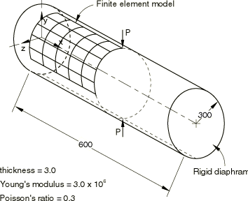
The geometry and material properties used for the example are shown in Figure 1. No units are specified since the values given are in a self-consistent set of units. The thickness of the cylinder is 1/100 of its radius, so the structure can be considered a thin shell. The mesh covers a symmetric segment of the cylinder, as indicated in the figure, with symmetry boundary conditions imposed on three edges of the mesh, while the fourth edge (the end of the cylinder) is supported by a rigid diaphragm.
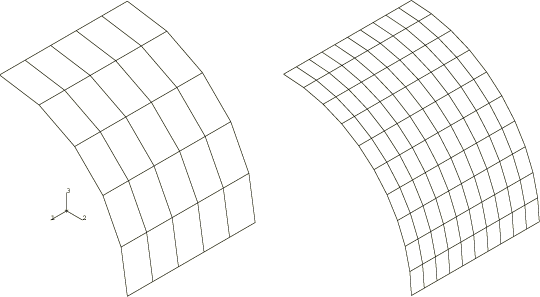
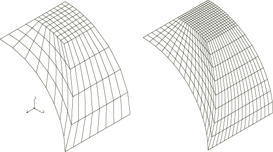
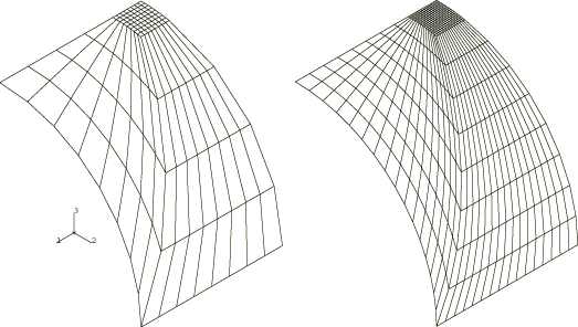
Two mesh patterns are used in this example: a regular mesh, shown in Figure 2, and two types of irregular meshes (coarse and fine), shown in Figure 3 and Figure 4. When triangular elements are used, each quadrilateral is divided into two triangles. The irregular meshes are tested because such mesh patterns might be used in cases where local effects must be modeled, and they allow an assessment to be made of the distortion sensitivity of the elements. For comparison, the cylinder is analyzed with all the general shell elements available in Abaqus/Standard; the Abaqus/Explicit analyses test only the S3R and S4R elements.
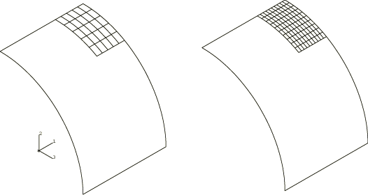
The submodeling capability in Abaqus/Standard is also used in this example to analyze the region in the vicinity of the concentrated load. For shell-to-shell submodeling two regular mesh patterns of S8R elements, shown in Figure 5, are driven by various global analyses also using regular meshes. In each case symmetry boundary conditions are imposed on two edges of the mesh, while results from the global analyses are interpolated to the remaining two edges through the submodeling technique. A shell-to-solid submodel is also available for demonstration purposes.
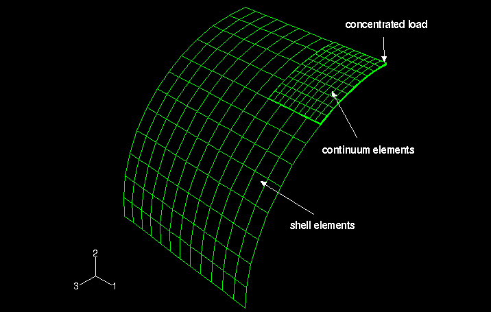
The shell-to-solid coupling capability in Abaqus/Standard and Abaqus/Explicit is also used in this example. The region in the vicinity of the concentrated load is meshed with continuum elements, and the rest of the cylinder is meshed with shell elements (see Figure 6). S4R, S8R, C3D8I, C3D10, C3D10HS, and C3D20R elements are used in six different shell-to-solid combinations in Abaqus/Standard; S4R and C3D8R elements are used in Abaqus/Explicit.
The displacements are small, so it is appropriate to ignore geometric nonlinearities in the Abaqus/Explicit analyses. If the large-displacement theory is activated by considering geometric nonlinearities, the results are unchanged in all cases since the strains and rotations remain small. However, the analysis CPU times typically increase by about 30%.
Two input files are provided for the continuum shell element model to illustrate orienting the element thickness (stacking) direction independent of the nodal connectivity using a cylindrical system.
![]()
Results and discussion
The result used for comparison is the radial displacement at the point where the pinching load is applied. The solution given by Lindberg et al., based on Flügge's (1973) series solution, is 0.1825 × 10⁻⁴.
Regular mesh
The results for the regular Abaqus/Standard mesh are shown in Table 1. The second-order elements (types S8R5 and S9R5) provide the most accurate solutions, whereas element type S8R (also a second-order element, but designed primarily for thick shell applications) provides a rather less accurate solution. Element type STRI3 provides the most accuracy among the first-order elements. None of the first-order elements provides acceptable solutions with the coarsest meshes used.
Element type STRI65 appears to converge rather slowly compared to the other element types. This result may appear counterintuitive, especially when compared to the STRI3 results, which demonstrate better convergence in this problem. Compared to STRI3, which is a flat facet element, element type STRI65 is preferable for modeling bending of thin shells and has complete quadratic representation of membrane strains; therefore, STRI65 is expected to perform better than STRI3 provided the number of elements in the two meshes is the same. In the present convergence study we have instead retained an equal number of nodes, which results in the relatively poor performance of the STRI65 element.
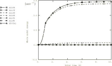
The results for the regular Abaqus/Explicit mesh are shown in Table 2. The results suggest that element types S3R and S4R are initially stiff but then converge to the correct solution. In addition, an energy plot is provided in Figure 7, which shows that by the end of the analysis a steady, static solution is obtained.
Irregular mesh
The second type of irregular mesh has more distorted element shapes than the first type of irregular mesh. The results for the two irregular Abaqus/Standard meshes are given in Table 3; and, as discussed in The barrel vault roof problem, they show less accurate results than the regular mesh problems.
Element types S8R5 and S9R5 again provide reasonably accurate results with fine meshes, although the coarse mesh results with these elements demonstrate poor accuracy. Interestingly, in this case all the first-order quadrilateral elements provide quite accurate values even with coarse meshing. This result may be fortuitous and should not be taken as a general indication of the quality of the elements in distorted meshes. For element type S4R both stiffness-based and enhanced hourglass controls are used to study the effect of mesh refinement and skew sensitivity. As expected, the coarse mesh results for enhanced hourglass control show poor accuracy compared with the fine mesh results.
The results for the irregular Abaqus/Explicit meshes are given in Table 4. These irregular meshes are more accurate in spite of the increased distortion because mesh refinement is concentrated in the area of highest solution gradients.
Submodeled analyses
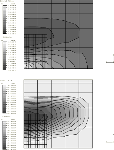
Results from the submodeled Abaqus/Standard analyses for the shell-to-shell cases are given in Table 5. Clearly, the submodeling technique provides a more accurate solution in the vicinity of the point load than the coarser global analyses. When S4R elements are used on the global level, the radial displacement at the point of load application is within 40% of Lindberg's solution for the coarse mesh and 13% for the finer mesh. The submodeling technique significantly improves these results, giving radial displacements in the shell submodels within 11% and 2% for all four combinations of meshes.
When S8R elements are used to mesh the quarter cylinder, solution accuracy improves from within 6% on the global level to within 0.7% on the submodel level. Displacement contours for the shell submodels are shown in Figure 8 for a representative analysis in which a 5 × 5 mesh of S8R elements is used on the global level and a 10 × 10 mesh of S8R elements is used on the submodel level.
Submodel analyses are tested with output from input files pinchcyl_s4r_reg55.inp, pinchcyl_s4r_reg1010.inp, and pinchcyl_s8r_reg55.inp. If five degree of freedom shells (S4R5, S8R5, etc.) are used at the global level, only the displacement degrees of freedom on the submodel boundary are driven since the rotations are not written to the results file for these elements.
A shell-to-solid submodel is also available for this problem, with a 10 × 10 C3D8I element mesh and four elements across the shell thickness. The submodel is driven from a 12 × 12 S4R element global model. The results are in good agreement with the shell-to-shell submodel results. Since the submodel in this case is made of solid elements, no comparison to the shell analytical solution is offered. The use of the shell-to-solid submodeling capability would be more justified in the case of concentrated loading applied on a finite area instead of the point load.
Shell-to-solid coupling analyses
Six shell-to-solid coupling cases are analyzed in Abaqus/Standard, as listed in Table 6. In all six cases a 12 × 12 shell element mesh is used. As is clearly seen, the shell-to-solid coupling analyses provide accurate solutions in the vicinity of the point load. The radial displacement at the point of load application is within 4.1% of Lindberg's solution for all six cases. As mentioned for submodeling, the use of the shell-to-solid coupling capability would be more justified in the case of concentrated loading applied on a finite area instead of the point load.
The results for the Abaqus/Explicit shell-to-solid coupling analysis are given in Table 7. The radial displacement at the point of load application is within 32% of Lindberg's solution.
![]()
Parametric study using the Abaqus parametric study capability
The performance of shell element formulations investigated in this example can be analyzed conveniently in a parametric study using the scripting capabilities offered in Abaqus. As an example we perform a parametric study in which eight analyses are automatically executed; these analyses correspond to combinations of three different (regular) mesh densities (5 × 5, 10 × 10, 20 × 20) for three different element types (S4, S8R, and S3R).
pinchcyl_parametric.inp shows the parametrized template input data used to generate the parametric variations of the parametric study. The script file (pinchcyl_parametric.psf) is used to perform the parametric study. The radial displacement at the point where the pinching load is applied is reported in the following table for each of the analyses of the parametric study:
   ________________________________________________

        Parametric study: pinchcyl_parametric
   ________________________________________________

           eltype,     m_density,     N2001_U.2,
   ________________________________________________

               S4,             5,  -9.51849e-06,
              S8R,             5,  -1.72138e-05,
               S4,            10,  -1.51895e-05,
              S8R,            10,  -1.80581e-05,
               S4,            20,   -1.7505e-05,
              S3R,             5,  -6.51879e-06,
              S3R,            10,   -1.3277e-05,
              S3R,            20,  -1.67431e-05,
   _______________________________________________
These results match the corresponding results found in Table 1.
![]()
Input files
Abaqus/Standard input files
- pinchcyl_s8r_submodel_reg55.inp
Regular submodel mesh, S8R elements.
- pinchcyl_s8r_sub_reg1010.inp
Submodel mesh, S8R elements.
- pinchcyl_c3d8i_sub_reg10104.inp
Solid submodel mesh, C3D8I elements.
- pinchcyl_s4r_c3d8i_shell2solid.inp
Shell-to-solid coupling model with S4R shell elements and C3D8I continuum elements.
- pinchcyl_s4r_c3d10_shell2solid.inp
Shell-to-solid coupling model with S4R shell elements and C3D10 continuum elements.
- pinchcyl_s4r_c3d10hs_shell2solid.inp
Shell-to-solid coupling model with S4R shell elements and C3D10HS continuum elements.
- pinchcyl_s4r_c3d20r_shell2solid.inp
Shell-to-solid coupling model with S4R shell elements and C3D20R continuum elements.
- pinchcyl_s8r_c3d8i_shell2solid.inp
Shell-to-solid coupling model with S8R shell elements and C3D8I continuum elements.
- pinchcyl_s8r_c3d10_shell2solid.inp
Shell-to-solid coupling model with S8R shell elements and C3D10 continuum elements.
- pinchcyl_s8r_c3d10hs_shell2solid.inp
Shell-to-solid coupling model with S8R shell elements and C3D10HS continuum elements.
- pinchcyl_s8r_c3d20r_shell2solid.inp
Shell-to-solid coupling model with S8R shell elements and C3D20R continuum elements.
- pinchcyl_parametric.inp
Parametrized template input data used to generate the parametric variations of the parametric study.
- pinchcyl_s3r_reg55.inp
5 × 5 mesh.
- pinchcyl_s3r_reg1010.inp
10 × 10 mesh.
- pinchcyl_s3r_reg2020.inp
20 × 20 mesh.
- pinchcyl_s3r_irreg_typ1.inp
Coarse irregular mesh (Type 1).
- pinchcyl_s3r_fineirreg_typ1.inp
Fine irregular mesh (Type 1).
- pinchcyl_s3r_irreg_typ2.inp
Coarse irregular mesh (Type 2).
- pinchcyl_s3r_fineirreg_typ2.inp
Fine irregular mesh (Type 2).
- pinchcyl_s4_reg55.inp
5 × 5 mesh.
- pinchcyl_s4_reg1010.inp
10 × 10 mesh.
- pinchcyl_s4_reg2020.inp
20 × 20 mesh.
- pinchcyl_s4_irreg_typ1.inp
Coarse irregular mesh (Type 1).
- pinchcyl_s4_fineirreg_typ1.inp
Fine irregular mesh (Type 1).
- pinchcyl_s4_irreg_typ2.inp
Coarse irregular mesh (Type 2).
- pinchcyl_s4_fineirreg_typ2.inp
Fine irregular mesh (Type 2).
- pinchcyl_s4_reg22_typ1.inp
2 × 2 mesh (Type 1).
- pinchcyl_s4_reg44_typ1.inp
4 × 4 mesh (Type 1).
- pinchcyl_s4_reg66_typ1.inp
6 × 6 mesh (Type 1).
- pinchcyl_s4_reg88_typ1.inp
8 × 8 mesh (Type 1).
- pinchcyl_s4_reg1212_typ1.inp
12 × 12 mesh (Type 1).
- pinchcyl_s4r_reg55.inp
5 × 5 mesh.
- pinchcyl_s4r_reg55_eh.inp
5 × 5 mesh with enhanced hourglass control.
- pinchcyl_s4r_reg1010.inp
10 × 10 mesh.
- pinchcyl_s4r_reg1010_eh.inp
10 × 10 mesh with enhanced hourglass control.
- pinchcyl_s4r_reg2020.inp
20 × 20 mesh.
- pinchcyl_s4r_reg2020_eh.inp
20 × 20 mesh with enhanced hourglass control.
- pinchcyl_s4r_irreg_typ1.inp
Coarse irregular mesh (Type 1).
- pinchcyl_s4r_irreg_typ1_eh.inp
Coarse irregular mesh with enhanced hourglass control (Type 1).
- pinchcyl_s4r_fineirreg_typ1.inp
Fine irregular mesh (Type 1).
- pinchcyl_s4r_fineirreg_typ1_eh.inp
Fine irregular mesh with enhanced hourglass control (Type 1).
- pinchcyl_s4r_irreg_typ2.inp
Coarse irregular mesh (Type 2).
- pinchcyl_s4r_irreg_typ2_eh.inp
Coarse irregular mesh with enhanced hourglass control (Type 2).
- pinchcyl_s4r_fineirreg_typ2.inp
Fine irregular mesh (Type 2).
- pinchcyl_s4r_fineirreg_typ2_eh.inp
Fine irregular mesh with enhanced hourglass control (Type 2).
- pinchcyl_s4r_reg22_typ1.inp
2 × 2 mesh (Type 1).
- pinchcyl_s4r_reg44_typ1.inp
4 × 4 mesh (Type 1).
- pinchcyl_s4r_reg66_typ1.inp
6 × 6 mesh (Type 1).
- pinchcyl_s4r_reg88_typ1.inp
8 × 8 mesh (Type 1).
- pinchcyl_s4r_reg1212_typ1.inp
12 × 12 mesh (Type 1).
- pinchcyl_s4r5_reg55.inp
5 × 5 mesh.
- pinchcyl_s4r5_reg1010.inp
10 × 10 mesh.
- pinchcyl_s4r5_reg2020.inp
20 × 20 mesh.
- pinchcyl_s4r5_irreg_typ1.inp
Coarse irregular mesh (Type 1).
- pinchcyl_s4r5_fineirreg_typ1.inp
Fine irregular mesh (Type 1).
- pinchcyl_s4r5_irreg_typ2.inp
Coarse irregular mesh (Type 2).
- pinchcyl_s4r5_fineirreg_typ2.inp
Fine irregular mesh (Type 2).
- pinchcyl_s4r5_reg22_typ1.inp
2 × 2 mesh (Type 1).
- pinchcyl_s4r5_reg44_typ1.inp
4 × 4 mesh (Type 1).
- pinchcyl_s4r5_reg66_typ1.inp
6 × 6 mesh (Type 1).
- pinchcyl_s4r5_reg88_typ1.inp
8 × 8 mesh (Type 1).
- pinchcyl_s4r5_reg1212_typ1.inp
12 × 12 mesh (Type 1).
- pinchcyl_s8r_reg55.inp
5 × 5 mesh.
- pinchcyl_s8r_reg1010.inp
10 × 10 mesh.
- pinchcyl_s8r_irreg_typ1.inp
Coarse irregular mesh (Type 1).
- pinchcyl_s8r_fineirreg_typ1.inp
Fine irregular mesh (Type 1).
- pinchcyl_s8r_irreg_typ2.inp
Coarse irregular mesh (Type 2).
- pinchcyl_s8r_fineirreg_typ2.inp
Fine irregular mesh (Type 2).
- pinchcyl_s8r5_reg55.inp
5 × 5 mesh.
- pinchcyl_s8r5_reg1010.inp
10 × 10 mesh.
- pinchcyl_s8r5_irreg.inp
Coarse irregular mesh (Type 1).
- pinchcyl_s8r5_fineirreg_typ1.inp
Fine irregular mesh (Type 1).
- pinchcyl_s8r5_irreg_typ2.inp
Coarse irregular mesh (Type 2).
- pinchcyl_s8r5_fineirreg_typ2.inp
Fine irregular mesh (Type 2).
- pinchcyl_s9r5_reg55.inp
5 × 5 mesh.
- pinchcyl_s9r5_reg1010.inp
10 × 10 mesh.
- pinchcyl_s9r5_irreg_typ1.inp
Coarse irregular mesh (Type 1).
- pinchcyl_s9r5_fineirreg_typ1.inp
Fine irregular mesh (Type 1).
- pinchcyl_s9r5_irreg_typ2.inp
Coarse irregular mesh (Type 2).
- pinchcyl_s9r5_fineirreg_typ2.inp
Fine irregular mesh (Type 2).
- pinchcyl_stri3_reg55.inp
5 × 5 mesh.
- pinchcyl_stri3_reg1010.inp
10 × 10 mesh.
- pinchcyl_stri3_reg2020.inp
20 × 20 mesh.
- pinchcyl_stri3_irreg_typ1.inp
Coarse irregular mesh (Type 1).
- pinchcyl_stri3_fineirreg_typ1.inp
Fine irregular mesh (Type 1).
- pinchcyl_stri3_irreg_typ2.inp
Coarse irregular mesh (Type 2).
- pinchcyl_stri3_fineirreg_typ2.inp
Fine irregular mesh (Type 2).
- pinchcyl_stri3_reg22_typ1.inp
2 × 2 mesh (Type 1).
- pinchcyl_stri3_reg44_typ1.inp
4 × 4 mesh (Type 1).
- pinchcyl_stri3_reg66_typ1.inp
6 × 6 mesh (Type 1).
- pinchcyl_stri3_reg88_typ1.inp
8 × 8 mesh (Type 1).
- pinchcyl_stri3_reg1212_typ1.inp
12 × 12 mesh (Type 1).
- pinchcyl_stri3_reg22_typ2.inp
2 × 2 mesh (Type 2).
- pinchcyl_stri3_reg44_typ2.inp
4 × 4 mesh (Type 2).
- pinchcyl_stri3_reg66_typ2.inp
6 × 6 mesh (Type 2).
- pinchcyl_stri3_reg88_typ2.inp
8 × 8 mesh (Type 2).
- pinchcyl_stri3_reg1212_typ2.inp
12 × 12 mesh (Type 2).
- pinchcyl_stri3_reg22_typ3.inp
2 × 2 mesh (Type 3).
- pinchcyl_stri3_reg44_typ3.inp
4 × 4 mesh (Type 3).
- pinchcyl_stri3_reg66_typ3.inp
6 × 6 mesh (Type 3).
- pinchcyl_stri3_reg88_typ3.inp
8 × 8 mesh (Type 3).
- pinchcyl_stri3_reg1212_typ3.inp
12 × 12 mesh (Type 3).
- pinchcyl_stri65_reg55.inp
5 × 5 mesh.
- pinchcyl_stri65_reg1010.inp
10 × 10 mesh.
- pinchcyl_stri65_irreg_typ1.inp
Coarse irregular mesh (Type 1).
- pinchcyl_stri65_fineirreg_typ1.inp
Fine irregular mesh (Type 1).
- pinchcyl_stri65_irreg_typ2.inp
Coarse irregular mesh (Type 2).
- pinchcyl_stri65_fineirreg_typ2.inp
Fine irregular mesh (Type 2).
- pinchcyl_sc6r_reg55.inp
5 × 5 mesh.
- pinchcyl_sc6r_reg1010.inp
10 × 10 mesh.
- pinchcyl_sc6r_reg2020.inp
20 × 20 mesh.
- pinchcyl_sc6r_stackdir_cylori.inp
20 × 20 mesh using the STACK DIRECTION=ORIENTATION parameter with a cylindrical orientation system to define the element thickness direction.
- pinchcyl_sc6r_irreg_typ1.inp
Coarse irregular mesh (Type 1).
- pinchcyl_sc6r_fineirreg_typ1.inp
Fine irregular mesh (Type 1).
- pinchcyl_sc6r_irreg_typ2.inp
Coarse irregular mesh (Type 2).
- pinchcyl_sc6r_fineirreg_typ2.inp
Fine irregular mesh (Type 2).
- pinchcyl_sc8r_reg55.inp
5 × 5 mesh.
- pinchcyl_sc8r_reg1010.inp
10 × 10 mesh.
- pinchcyl_sc8r_reg2020.inp
20 × 20 mesh.
- pinchcyl_sc8r_stackdir_cylori.inp
20 × 20 mesh using the STACK DIRECTION=ORIENTATION parameter with a cylindrical orientation system to define the element thickness direction.
- pinchcyl_sc8r_irreg_typ1.inp
Coarse irregular mesh (Type 1).
- pinchcyl_sc8r_fineirreg_typ1.inp
Fine irregular mesh (Type 1).
- pinchcyl_sc8r_irreg_typ2.inp
Coarse irregular mesh (Type 2).
- pinchcyl_sc8r_fineirreg_typ2.inp
Fine irregular mesh (Type 2).
Abaqus/Explicit input files
- pinchcyl_s4r_c3d8r_shell2solid.inp
Shell-to-solid coupling model with S4R shell elements and C3D8R continuum elements.
- pinch_cyl_coarse_irr1_s4r.inp
S4R element, coarse irregular mesh (Type 1).
- pinch_cyl_fine_irr1_s4r.inp
S4R element, fine irregular mesh (Type 1).
- pinch_cyl_coarse_irr1_s3r.inp
S3R element, coarse irregular mesh (Type 1).
- pinch_cyl_fine_irr1_s3r.inp
S3R element, fine irregular mesh (Type 1).
- pinch_cyl_coarse_reg_s4r.inp
S4R element, coarse regular mesh.
- pinch_cyl_med_reg_s4r.inp
S4R element, medium regular mesh.
- pinch_cyl_fine_reg_s4r.inp
S4R element, fine regular mesh.
- pinch_cyl_coarse_reg_s3r.inp
S3R element, coarse regular mesh.
- pinch_cyl_med_reg_s3r.inp
S3R element, medium regular mesh.
- pinch_cyl_fine_reg_s3r.inp
S3R element, fine regular mesh.
- pinch_cyl_coarse_irr1_s4r_lk.inp
S4R element, coarse irregular mesh (Type 1).
- pinch_cyl_fine_irr1_s4r_lk.inp
S4R element, fine irregular mesh (Type 1).
- pinch_cyl_coarse_irr1_s3r_lk.inp
S3R element, coarse irregular mesh (Type 1).
- pinch_cyl_fine_irr1_s3r_lk.inp
S3R element, fine irregular mesh (Type 1).
- pinch_cyl_coarse_reg_s4r_lk.inp
S4R element, coarse regular mesh.
- pinch_cyl_med_reg_s4r_lk.inp
S4R element, medium regular mesh.
- pinch_cyl_fine_reg_s4r_lk.inp
S4R element, fine regular mesh.
- pinch_cyl_coarse_reg_s3r_lk.inp
S3R element, coarse regular mesh.
- pinch_cyl_med_reg_s3r_lk.inp
S3R element, medium regular mesh.
- pinch_cyl_fine_reg_s3r_lk.inp
S3R element, fine regular mesh.
![]()
References
- Stresses in Shells, Springer-Verlag, New York, Second, 1973.
- “New Developments in the Finite Element Analysis of Shells,” Quarterly Bulletin of the Division of Mechanical Engineering and the National Aeronautical Establishment, National Research Council of Canada, vol. 4, 1969.
![]()
Tables
| Element type | Number of dof | Displacement | Error (compared to 1.825 × 10⁻⁵) |
|---|---|---|---|
| (× 10−5) | |||
| STRI3 | 216 | 1.134 | −38% |
| 726 | 1.696 | −7% | |
| 2646 | 1.829 | 0.2% | |
| S4R5 | 216 | 1.099 | −40% |
| 726 | 1.597 | −12% | |
| 2646 | 1.778 | −2.6% | |
| S4 | 216 | 0.951 | −47.8% |
| 726 | 1.519 | −16.7% | |
| 2646 | 1.750 | −4.0% | |
| S4R | 216 | 1.089 | −40.3% |
| 726 | 1.591 | −12.8% | |
| 2646 | 1.779 | −2.5% | |
| S4R* | 216 | 0.954 | –47.7% |
| 726 | 1.525 | –16.4% | |
| 2646 | 1.755 | –3.8% | |
| S8R5 | 726 | 1.804 | −1.1% |
| 2646 | 1.833 | 0.4% | |
| S8R | 576 | 1.721 | −5.7% |
| 2046 | 1.806 | −1% | |
| S9R5 | 726 | 1.804 | −1.1% |
| 2646 | 1.833 | 0.4% | |
| STRI65 | 726 | 1.358 | −25.6% |
| 2646 | 1.765 | −3.3% | |
| S3R | 216 | 0.653 | −64% |
| 726 | 1.328 | −27% | |
| 2646 | 1.674 | −8.3% | |
| SC6R | 216 | 0.652 | –65.7% |
| 726 | 1.327 | –27.3% | |
| 2649 | 1.673 | –8.3% | |
| SC8R | 216 | 1.123 | –38.5% |
| 726 | 1.608 | –11.9% | |
| 2649 | 1.784 | –2.25% | |
| *Abaqus/Standard finite-strain element with enhanced hourglass control. | |||
| Element type | Number of elements | Displacement | Error (compared to 1.825 × 10⁻⁵) |
|---|---|---|---|
| (× 10−5) | |||
| S3R | 50 | 0.767 | −58.% |
| 200 | 1.390 | −24.% | |
| 800 | 1.703 | −6.7% | |
| S4R | 25 | 1.115 | −39.% |
| 100 | 1.616 | −11.% | |
| 400 | 1.806 | −1.0% |
| Element | Number of dof | Mesh type 1 | Error | Mesh type 2 | Error |
|---|---|---|---|---|---|
| type | Displacement | Displacement | |||
| (× 10−5) | (× 10−5) | ||||
| STRI3 | 894 | 1.767 | −3.2% | 1.372 | −25% |
| 3318 | 1.810 | −0.8% | 1.663 | −9% | |
| S4R5 | 894 | 1.815 | −0.5% | 1.790 | −1.9% |
| 3318 | 1.835 | 0.5% | 1.842 | 0.9% | |
| S4R | 894 | 1.814 | −0.6% | 1.781 | −2.4% |
| 3318 | 1.849 | 1.3% | 1.862 | 2.0% | |
| S4R* | 894 | 1.764 | –3.3% | 1.618 | –10.7% |
| 3318 | 1.840 | 0.8% | 1.845 | 1.1% | |
| S4 | 894 | 1.687 | −7.52% | 1.454 | −20.3% |
| 3318 | 1.814 | −0.58% | 1.777 | −2.5% | |
| S8R5 | 918 | 1.803 | −1.2% | 1.519 | −17% |
| 3366 | 1.793 | −1.8% | 1.793 | −1.8% | |
| S8R | 702 | 1.664 | −9% | 1.244 | −32% |
| 2550 | 1.726 | −5.4% | 1.726 | −5.4% | |
| S9R5 | 918 | 1.793 | −1.8% | 1.504 | −18% |
| 3366 | 1.831 | 0.3% | 1.774 | −2.8% | |
| STRI65 | 918 | 1.723 | −5.6% | 1.551 | −15.01% |
| 3366 | 1.850 | 1.4% | 1.824 | −0.05% | |
| S3R | 894 | 1.565 | −14% | 1.270 | −30% |
| 3318 | 1.763 | −3.4% | 1.654 | −9.4% | |
| SC6R | 894 | 1.563 | –14.3% | 1.273 | –30.2% |
| 3318 | 1.762 | –3.4% | 1.655 | –9.3% | |
| SC8R | 894 | 1.821 | –0.22% | 1.767 | –3.18% |
| 3318 | 1.850 | 1.37% | 1.865 | 2.19% | |
| * Abaqus/Standard finite-strain element with enhanced hourglass control. | |||||
| Element type | Number of elements | Displacement | Error (compared to 1.825 × 10⁻⁵) |
|---|---|---|---|
| (× 10−5) | |||
| S3R | 256 | 1.618 | −11.3% |
| 1024 | 1.794 | −1.69% | |
| S4R | 128 | 1.848 | 1.24% |
| 512 | 1.883 | 3.17% |
| Global | Global | Submodel | Displacement | Error |
|---|---|---|---|---|
| Element Type | Mesh Size | Mesh Size | (× 10−5) | |
| S4R | 5 × 5 | n/a | 1.092 | −40.2% |
| 5 × 5 | 1.6139 | −11.6% | ||
| 10 × 10 | 1.6259 | −10.9% | ||
| 10 × 10 | n/a | 1.592 | −12.8% | |
| 5 × 5 | 1.7775 | −2.6% | ||
| 10 × 10 | 1.7881 | −2.0% | ||
| S8R | 5 × 5 | n/a | 1.721 | −5.7% |
| 5 × 5 | 1.8004 | −1.3% | ||
| 10 × 10 | 1.8123 | −0.7% |
| Shell element | Continuum element | Displacement | Error (compared to 1.825 × 10⁻⁵) |
|---|---|---|---|
| (× 10−5) | |||
| S4R | C3D8I | 1.750 | −4.11% |
| S4R | C3D10 | 1.775 | −2.74% |
| S4R | C3D10HS | 1.775 | –2.74% |
| S4R | C3D20R | 1.837 | 0.656% |
| S8R | C3D8I | 1.766 | −3.23% |
| S8R | C3D10 | 1.797 | −1.53% |
| S8R | C3D10HS | 1.797 | –1.53% |
| S8R | C3D20R | 1.854 | 1.59% |
| Shell element | Continuum element | Displacement | Error (compared to 1.825 × 10⁻⁵) |
|---|---|---|---|
| (× 10−5) | |||
| S4R | C3D8R | 1.24 | −32% |
![]()
Figures