Eigenvalue analysis of a cantilever plate | ||
| ||
ProductsAbaqus/Standard
Problem description
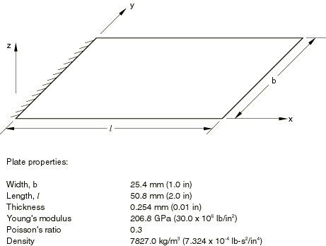
The properties of the plate are shown in Figure 1. The analyses involve three different meshes: 2 × 4, 5 × 10, and 10 × 20, where the smaller number of elements is used across the width of the plate. The following shell elements are used with each mesh: S3R, S4R5, S8R5, S9R5, STRI65, STRI3, S4R, S4, and S8R. The meshes used with the triangular elements are based on dividing each rectangle into two triangles.
![]()
Results and discussion
The series solution developed by Barton (1951) is used by Zienkiewicz (1971) for a study similar to this example. Here a thinner plate is used than the one described by Zienkiewicz (1971), because the theoretical solution is a thin plate solution, and we wish to ensure that element types STRI65, S9R5, S8R5, S4R5, S8R, S4R, and S4 (which include transverse shear strain energy in penalty form) provide comparable results. If the thicker plate was used, the shear flexibility in these elements would cause their predictions to be different from the thin-plate solutions.
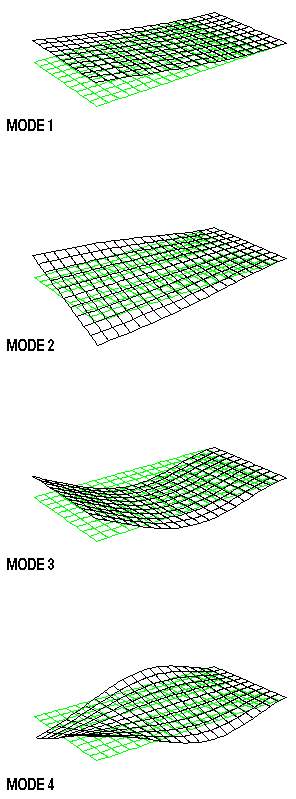
The second-order shell elements (S9R5, STRI65, S8R5, and S8R) all give essentially convergent values for the first four frequencies, even with the 2 × 4 mesh. (Here we mean convergence with respect to the number of elements used and base this conclusion on the observation that the frequency values are not changing significantly as the mesh is refined.) S8R shows some reduction in frequency in the fourth mode as the mesh is refined: presumably this is caused by transverse shear flexibility affecting the result. For the first-order elements (S4R5, S4R, S4, S3R, and STRI3) all the meshes give quite good values for the frequencies, except for S3R elements. Due to constant bending strain approximations, S3R elements require a finer mesh for good accuracy, which is evident from the results. For the same number of degrees of freedom the second-order elements give better results for the higher modes than the first-order elements. The mode shapes are shown in Figure 2.
![]()
Input files
- eigenvalueplate_s3r_coarse.inp
-
Element type S3R, 2 × 4 mesh.
- eigenvalueplate_s3r_fine.inp
-
Element type S3R, 5 × 10 mesh.
- eigenvalueplate_s3r_finer.inp
-
Element type S3R, 10 × 20 mesh.
- eigenvalueplate_s4_coarse.inp
-
Element type S4, 2 × 4 mesh.
- eigenvalueplate_s4_fine.inp
-
Element type S4, 5 × 10 mesh.
- eigenvalueplate_s4_finer.inp
-
Element type S4, 10 × 20 mesh.
- eigenvalueplate_s4r_coarse.inp
-
Element type S4R, 2 × 4 mesh.
- eigenvalueplate_s4r_fine.inp
-
Element type S4R, 5 × 10 mesh.
- eigenvalueplate_s4r_finer.inp
-
Element type S4R, 10 × 20 mesh.
- eigenvalueplate_s4r5_coarse.inp
-
Element type S4R5, 2 × 4 mesh.
- eigenvalueplate_s4r5_fine.inp
-
Element type S4R5, 5 × 10 mesh.
- eigenvalueplate_s4r5_finer.inp
-
Element type S4R5, 10 × 20 mesh.
- eigenvalueplate_s8r_coarse.inp
-
Element type S8R, 2 × 4 mesh.
- eigenvalueplate_s8r_fine.inp
-
Element type S8R, 5 × 10 mesh.
- eigenvalueplate_s8r_finer.inp
-
Element type S8R, 10 × 20 mesh.
- eigenvalueplate_s8r5_coarse.inp
-
Element type S8R5, 2 × 4 mesh.
- eigenvalueplate_s8r5_fine.inp
-
Element type S8R5, 5 × 10 mesh.
- eigenvalueplate_s8r5_finer.inp
-
Element type S8R5, 10 × 20 mesh.
- eigenvalueplate_s9r5_coarse.inp
-
Element type S9R5, 2 × 4 mesh.
- eigenvalueplate_s9r5_fine.inp
-
Element type S9R5, 5 × 10 mesh.
- eigenvalueplate_s9r5_finer.inp
-
Element type S9R5, 10 × 20 mesh.
- eigenvalueplate_stri3_coarse.inp
-
Element type STRI3, 2 × 4 mesh.
- eigenvalueplate_stri3_fine.inp
-
Element type STRI3, 5 × 10 mesh.
- eigenvalueplate_stri3_finer.inp
-
Element type STRI3, 10 × 20 mesh.
- eigenvalueplate_stri65_coarse.inp
-
Element type STRI65, 2 × 4 mesh.
- eigenvalueplate_stri65_fine.inp
-
Element type STRI65, 5 × 10 mesh.
- eigenvalueplate_stri65_finer.inp
-
Element type STRI65, 10 × 20 mesh.
![]()
References
- “Vibrations of Rectangular and Shear Plates,” Journal of Applied Mechanics, vol. 18, pp. 129–134, 1951.
- The Finite Element Method in Engineering Science, McGraw-Hill, London, 1971.
![]()
Tables
| Mode | 1 | 2 | 3 | 4 |
|---|---|---|---|---|
| Series Solution | 84.6 | 363.8 | 526.6 | 1187.0 |
| S3R | ||||
| 2 × 4 (90) | 91.5 | 539.9 | 653.7 | 1811.8 |
| 5 × 10 (396) | 86.8 | 401.1 | 549.8 | 1374.9 |
| 10 × 20 (1386) | 85.1 | 367.8 | 532.1 | 1210.0 |
| S4 | ||||
| 2 × 4 (90) | 84.7 | 367.5 | 610.6 | 1324.1 |
| 5 × 10 (396) | 84.0 | 361.9 | 535.7 | 1198.9 |
| 10 × 20 (1386) | 83.9 | 360.8 | 525.6 | 1179.5 |
| S4R | ||||
| 2 × 4 (90) | 84.2 | 357.2 | 609.5 | 1257.5 |
| 5 × 10 (396) | 83.9 | 360.4 | 535.3 | 1189.7 |
| 10 × 20 (1386) | 83.8 | 360.4 | 525.4 | 1177.2 |
| S4R5 | ||||
| 2 × 4 (90) | 84.2 | 356.3 | 609.3 | 1251.6 |
| 5 × 10 (396) | 83.9 | 360.4 | 535.3 | 1189.6 |
| 10 × 20 (1386) | 83.8 | 360.5 | 525.4 | 1177.5 |
| S8R | ||||
| 2 × 4 (222) | 83.8 | 361.2 | 525.5 | 1183.8 |
| 5 × 10 (1086) | 83.9 | 360.4 | 522.5 | 1172.9 |
| 10 × 20 (3966) | 83.8 | 359.7 | 522.2 | 1170.9 |
| S8R5 | ||||
| 2 × 4 (270) | 83.8 | 360.6 | 523.8 | 1176.6 |
| 5 × 10 (1386) | 83.8 | 360.6 | 522.4 | 1173.7 |
| 10 × 20 (5166) | 83.8 | 360.5 | 522.2 | 1173.2 |
| S9R5 | ||||
| 2 × 4 (270) | 83.8 | 360.6 | 523.8 | 1176.6 |
| 5 × 10 (1386) | 83.8 | 360.6 | 522.4 | 1173.7 |
| 10 × 20 (5166) | 83.8 | 360.5 | 522.2 | 1173.2 |
| STRI3 | ||||
| 2 × 4 (90) | 81.6 | 298.9 | 473.7 | 928.2 |
| 5 × 10 (396) | 83.5 | 348.2 | 514.1 | 1130.0 |
| 10 × 20 (1386) | 83.7 | 357.4 | 520.3 | 1163.0 |
| STRI65 | ||||
| 2 × 4 (270) | 84.1 | 368.1 | 524.0 | 1229.1 |
| 5 × 10 (1386) | 83.9 | 360.9 | 521.8 | 1175.4 |
| 10 × 20 (5166) | 83.8 | 360.5 | 522.2 | 1172.9 |
| The grid size specification is followed by the number of degrees of freedom in the model. | ||||
![]()
Figures