Link and coupling conditions overview | ||||||
|
| |||||
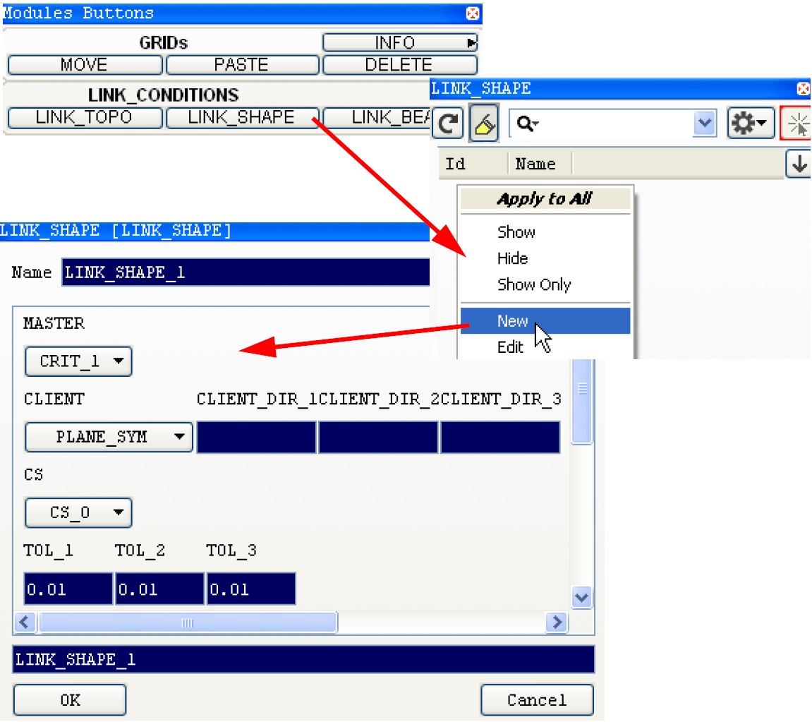
- In Tosca ANSA® environment, Link conditions are defined using the Modules Buttons
toolbar:
Select LINK_SHAPE on LINK_CONDITIONS panel, then click New.
- In Tosca Structure.gui, select .
- In Tosca ANSA® environment, link definitions are visualized graphically in the model view.
Each link condition has a name (ID_NAME parameter). A criterion for determining the master node (MASTER parameter) is defined as well as a rule for the displacement of the client nodes (CLIENT parameter).
A typical LINK_SHAPE command appears as follows:
      LINK_SHAPE
        ID_NAME = name_of_link_shape
        MASTER = ...
        CLIENT = ...
        ...
      END_
Depending on the selected CLIENT parameter, other parameters are also required. In some circumstances a coordinate system (CS parameter) or tolerances (TOL parameter) must be specified. These parameters of a LINK_SHAPE command may appear as follows:
      LINK_SHAPE
        ...
        CS = name_of_coord_system
        TOL = <tol_1>, <tol_2>, <tol_3>
      END_
In the following subsections the MASTER and CLIENT parameters are described in detail. The CS and TOL parameters are also described when applicable.
 |
Link conditions basically only define a coupling rule without referencing a specific node group. The coupling condition is assigned to a node group after activation with CHECK_LINK in the DVCON_SHAPE command.
- In Tosca ANSA® environment, the link definition can be chosen after typing a "?" in the CHECK_LINK field (click DVCON_SHAPE in RESTRICTIONS panel of Modules Buttons toolbar, then click New so that the window with the design variable constraint settings appears).
- In Tosca Structure.gui the link condition is assigned in the drop down menu of the DVCON_SHAPE command.
Important:
|
Determining the master node (MASTER)
The MASTER parameter is used in each definition of a link condition to specify how to determine the master node. This node prescribes the displacement of the nodes affected by the link condition. It can be set explicitly by the user:
MASTER = NODE, node_nr
This causes the master displacement to be determined from the same node during the entire optimization.
Furthermore the master node may be determined from a master node group. This allows the user to define a components edge to be the master edge for optimization. The algorithm will determine the master node automatically from the master node group. In this case the master node group must contain exactly one node of each link group.
MASTER = NDGR, <nodegroup>
Another way is to have the system automatically determine the master node according to two different criteria:
MASTER = MAX
or
MASTER = MIN
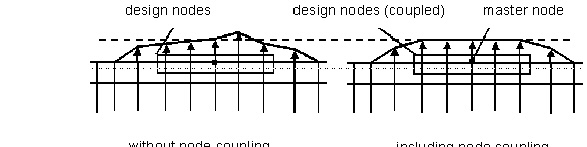
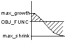
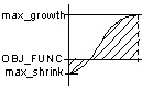
In this case, the master node is re-determined in every cycle. When the master node is automatically determined, the critical factor is identifying which node displacement (determined by the stress) for the coupling group is relevant. Principally, there exist four different cases of how the largest and smallest node displacements relate to the reference value within the node group:
- Case 1: The stress everywhere is greater than the reference value, i.e., a positive displacement is determined for all design nodes of the coupling group. All design nodes will grow out of the component.
- Case 2: The stress everywhere is less than the reference value, i.e., for all design nodes of the coupling group a negative displacement is determined. All design nodes will shrink inwards.
- Case 3: There are nodes with greater and less stress than the reference value and the absolute shrinkage is greater than the absolute growth (abs(max_neg) > abs(max_pos)).
- Case 4: There are nodes with greater and less stress than the reference value and the absolute shrinkage is less than the absolute growth (abs(max_neg) < abs(max_pos)).
|
Case 1 |
Case 2 |
Case 3 |
Case 4 |
|
|
ALL_GROWTH |
ALL_SHRINK |
MORE_SHRINK |
MORE_GROWTH |
|
 |
 |
 |
 |
|
|
lab1 = |
Selected Master Displacement Value |
|||
|
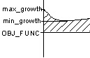
MAX |
max_growth |
min_shrink |
max_growth |
max_growth |
|
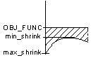
MIN |
min_growth |
max_shrink |
max_shrink |
max_shrink |
The two criteria MAX and MIN, respectively, select different master nodes corresponding to the selected displacement values:
- MAX The MAX-Criterion is the conservative option. Here, the maximum growth (as in the cases 1, 3, 4) or the smallest shrinkage (as in case 2) is always used to select the master node. This is the standard criterion for shape optimization.
- MIN The MIN-Criterion moves the component surface inward as far as possible. This criterion has to be used when linking conditions are required while optimizing contact surfaces.
Note:
- CHECK_LINK in the DVCON_SHAPE command assigns the link condition to a node group. For MASTER=NODE, node_nr, the explicitly declared node must not necessarily be contained in the node group. For MASTER=MAX or MASTER= MIN , the master node is always determined from the nodes of the node group.
- Older parameters CRIT_1 and CRIT_2 correspond to MAX and MIN respectively. With SIMULIA Tosca Structure 2017 these older definitions are still supported.
![]()
Displacement of the client nodes (CLIENT)
The CLIENT parameter is used in each definition of a link condition to set a rule for determining the displacement of the client nodes based on the displacement of the master node. The client nodes are moved relative to the master node. The following rules can be selected:
- Plane symmetry (PLANE_SYM)
- Plane symmetry for non-symmetric meshes (SURF_PLANE_SYM)
- Cyclic symmetry for non-symmetric meshes (SURF_CYCLIC_SYM)
- Cyclic-plane symmetry combination (SURF_CYCLIC_PLANE_SYM)
- Point symmetry (POINT_SYM)
- Rotational symmetry (ROTATION_SYM)
- Coupling displacement coordinates (VECTOR)
- Coupling displacement direction (DIRECTION)
- Coupling amount of displacement (LENGTH)
- Coupling coordinates in the FE displacement coordinate system (DISP_CS)
- Stampable surface (SURF_STAMP)
- Turnable surface (SURF_TURN)
- Drillable surface (SURF_DRILL)
- Demoldable surface (SURF_DEMOLD)
- Restricting displacement to a slide surface (FREE_FORM)
The individual rules for determining the client displacements are described in detail in the linked chapters.
Not all link conditions are applicable for both, the controller and the sensitivity based shape optimization approach. The table below shows which types are usable with which approach.
| CLIENT / Applicable for | Controller (SHAPE_CONTROLLER) | Sensitivity (SHAPE_SENSITIVITY) |
|---|---|---|
| PLANE_SYM | OK | - |
| SURF_PLANE_SYM | OK | OK |
| SURF_CYCLIC_SYM | OK | - |
| SURF_CYCLIC_PLANE_SYM | OK | - |
| POINT_SYM | OK | - |
| ROTATIONAL_SYM | OK | - |
| VECTOR | OK | - |
| DIRECTION | OK | - |
| LENGTH | OK | - |
| DISP_CS | OK | - |
| SURF_STAMP | OK | - |
| SURF_TURN | OK | - |
| SURF_DRILL | OK | - |
| SURF_DEMOLD | OK | OK |
| FREE_FORM | OK | - |
![]()
Example: Link condition with fixed master node
All nodes of the previously defined node group node_rigid should have the same displacement with respect to the global Cartesian coordinate system as the design node with the number 46. Node 46 need not be a part of the node group node_rigid. The link condition should have the name link_rigid. The link condition is then used in the restriction with the name dvcon_rigid.
        LINK_SHAPE
          ID_NAME = link_rigid
          MASTER = NODE, 46
          CLIENT = VECTOR
          CS = CS_0
        END_
        DVCON_SHAPE
          ID_NAME = dvcon_rigid
          ND_GROUP = node_rigid
          CHECK_LINK = link_rigid
        END_
![]()
Example: Coupling condition with automatic determination of the master node
All nodes of the node group ndgr_left should have the same displacement as the node from ndgr_left that has the greatest outward displacement. In the same way, all nodes of the node group ndgr_right should have the same displacement as the node from ndgr_right that has the greatest outward displacement. This requires a link condition and two restrictions.
        LINK_SHAPE
        ID_NAME = link_left_or_right
          MASTER = MAX
          CLIENT = VECTOR
          CS = CS_0
        END_
        DVCON_SHAPE
        ID_NAME = dvcon_left
          ND_GROUP = ndgr_left
          CHECK_LINK = link_left_or_right
        END_

        DVCON_SHAPE
        ID_NAME = dvcon_right
          ND_GROUP = ndgr_right
          CHECK_LINK = link_left_or_right
        END_
In each design cycle the system identifies which nodes in each of the node groups, ndgr_left and ndgr_right, has the greatest positive displacement (in the growth direction). Usually, these are the nodes with the largest stress difference between the effective value and the targeted value. These displacements are then applied to all nodes of the node groups ndgr_left and ndgr_right, respectively. The following command can be used instead of the two individual DVCON_SHAPE commands:
        DVCON_AUTO_SHAPE
        ID_NAME = dvcon_*
          ND_GROUP_FAMILY = ndgr_*
          CHECK_LINK = link_left_or_right
        END_
The naming left and right is determined automatically from the complete name of the node groups and added to the root name of the automatically generated DVCON_SHAPE entries. However, this requires that only these two node groups begin with the name ndgr_ otherwise other node groups will be taken into consideration.