LINK_SHAPE | ||
| ||
ID_NAME |
= <id_name_of_link_shape> |
Name of LINK_SHAPE definition. |
MASTER |
Determination of the master node | |
= MAX |
Maximum growth and minimum shrinkage. Allowed for all CLIENT types. |
|
= MIN |
Maximum shrinkage and minimum growth. Allowed for all CLIENT types. |
|
= NODE, <node_nr> |
Node <node_nr> is the master node. Only allowed for the following CLIENT types: PLANE_SYM POINT_SYM VECTOR DIRECTION LENGTH DISP_CS. |
|
= NDGR, <node_group> |
Master is determined from the nodegroup <node_group>. From each link-shape group, one node must exist in the master group. Only allowed for the following CLIENT types: PLANE_SYM POINT_SYM ROTATION_SYM DIRECTION DISP_CS SURF_TURN FREE_FORM VECTOR LENGTH. |
|
CLIENT |
Determination rule for the client nodes: |
|
= PLANE_SYM, AXIS_1 = PLANE_SYM, AXIS_2 = PLANE_SYM, AXIS_3 |
A symmetrical displacement of the nodes referring to the plane which lies normal to the given axis of the coordinate system. |
|
= POINT_SYM |
A symmetrical displacement of the nodes referring to the origin of the coordinate system is enforced. |
|
= ROTATION_SYM, AXIS_1 = ROTATION_SYM, AXIS_2 = ROTATION_SYM, AXIS_3 |
A rotational symmetric displacement of the nodes referring to the given axis of the coordinate system is enforced. |
|
= VECTOR = VECTOR,ON/OFF,ON/OFF,ON/OFF |
All displacement components are coupled. The choice of which components to couple and which not to couple is done using the ON or OFF switch. The first switch controls the first component etc. |
|
= DIRECTION |
All displacement components are coupled. The resulting displacement vector is scaled to the original absolute value of displacement. |
|
= LENGTH |
Only the amount of displacement is coupled. |
|
= DISP_CS = DISP_CS,ON/OFF,ON/OFF,ON/OFF |
The displacement is coupled in the relevant displacement coordinate system. The choice of which components to couple and which not to couple is done using the ON or OFF switch. The first switch controls the first component etc. |
|
= SURF_STAMP, AXIS_1 = SURF_STAMP, AXIS_2 = SURF_STAMP, AXIS_3 |
Conserve a stampable surface. The stamping direction is defined via the axis of the coordinate system. |
|
= SURF_TURN, AXIS_1 = SURF_TURN, AXIS_2 = SURF_TURN, AXIS_3 |
Conserve a turnable surface. The rotation axis is defined via the coordinate system axis. |
|
= SURF_DRILL, AXIS_1 = SURF_DRILL, AXIS_2 = SURF_DRILL, AXIS_3 |
Conserve a drillable surface. The generated surface is demoldable and turnable. The drilling axis is defined via the coordinate system axis. |
|
= SURF_DEMOLD, AXIS_1 = SURF_DEMOLD, AXIS_2 = SURF_DEMOLD, AXIS_3 |
Conserve a demoldable surface for casting. The demold direction is defined via the coordinate system axis. |
|
Determination rule for the client nodes with CLIENT_DIR or DEMOLD_DIR parameter: |
||
= PLANE_SYM |
A symmetrical displacement of the nodes referring to the plane which lies normal to the axis specified by CLIENT_DIR. |
|
= ROTATION_SYM |
Conserve a rotational symmetric surface with rotational symmetric mesh. Symmetry groups are determined automatically according to the axis specified by CLIENT_DIR parameter. |
|
= SURF_PLANE_SYM |
Conserve plane symmetry for non-symmetric meshes. The symmetry axis is defined via CLIENT_DIR. |
|
= SURF_CYCLIC_SYM |
Conserve cyclic symmetry for non-symmetric meshes. |
|
= SURF_CYCLIC_PLANE_SYM |
Conserve cyclic and plane symmetry for non-symmetric meshes simultaneously. |
|
= SURF_STAMP |
Conserve a stampable surface. The stamping direction is defined via the CLIENT_DIR parameter. An additional demold direction can be defined using DEMOLD_DIR. |
|
= SURF_TURN |
Conserve a turnable surface. The rotation axis is defined via the CLIENT_DIR parameter. |
|
= SURF_DRILL |
Conserve a drillable surface. The generated surface is demoldable and turnable. The drilling axis is defined via the CLIENT_DIR parameter. |
|
= SURF_DEMOLD |
Conserve a demoldable surface for casting. The demold direction is defined via the DEMOLD_DIR parameter. (CLIENT_DIR is also supported, but not recommended). |
|
= FREE_FORM |
The node group referenced via MASTER=NDGR, <node_group> defines a free form surface; Can only be used if this command is referenced via DVCON_SHAPE, CHECK_SLIDE. |
|
CLIENT_DIR |
= <x_1>, <x_2>, <x_3> |
Direction of the axis for the restrictions PLANE_SYM, ROTATION_SYM, SURF_STAMP, SURF_TURN, SURF_DRILL, SURF_DEMOLD, SURF_PLANE_SYM, SURF_CYCLIC_SYM, SURF_CYCLIC_PLANE_SYM with reference to the specified coordinate system. |
DEMOLD_DIR |
= <x_1>, <x_2>, <x_3> |
Demolding direction for the restrictions SURF_STAMP and SURF_DEMOLD (CLIENT_DIR also possible) with reference to the specified coordinate system. |
CS |
= <name_of_coord_system> |
Name of the coordinate system in which the link condition is defined (i.e. which the axis or CLIENT_DIR/DEMOLD_DIR refer to). |
TOL |
= <tol_1>, <tol_2>, <tol_3> |
Tolerances in the three axial directions for symmetrical recognition of CLIENT = PLANE_SYM, POINT_SYM, ROTATION_SYM, SURF_STAMP, SURF_TURN, SURF_DRILL, SURF_PLANE_SYM, SURF_CYCLIC_SYM, SURF_CYCLIC_PLANE_SYM or SURF_DEMOLD. |
Special items for CLIENT parameters
Not all entries are allowed for each parameter as shown in the following table:
SURF_STAMP |
SURF_TURN |
SURF_DRILL |
SURF_DEMOLD |
ROTATION_SYM |
SURF_CYCLIC_SYM |
SURF_CYCLIC_PLANE_SYM |
|
|---|---|---|---|---|---|---|---|
SURF_PARAM |
x |
x x |
x |
- |
- |
- |
- |
SURF_SYM_TYPE |
x |
x |
x |
- |
- |
- |
- |
SURF_SYM_CS |
x |
x |
x |
- |
- |
- |
- |
SURF_SYM_NDGR |
x |
x |
x |
- |
- |
- |
- |
ANGLE |
x |
- |
x |
x |
x |
x |
x |
UNDERCUT_TOL |
- |
- |
x |
x |
- |
- |
- |
CHECK_GROUP |
- |
- |
- |
x |
- |
- |
- |
CYCLIC_SYM_START |
- |
- |
- |
- |
- |
x |
x |
SURF_PARAM |
= <master_areas>, <net_points> |
Parameters for the surface algorithms with 4 < net_points < master_areas - 10%. |
SURF_SYM_TYPE |
= PLANE_SYM, AXIS_1 = PLANE_SYM, AXIS_2 = PLANE_SYM, AXIS_3 |
Plane symmetry linking for surfaces defined with the SURF_* parameters. |
= POINT_SYM |
Point symmetry linking for surfaces defined with the SURF_* parameters. |
|
SURF_SYM_CS |
= <name_of_cs> |
Name of the coordinate system for the SURF_SYM symmetry linking. |
SURF_SYM_NDGR |
= <name_of_nodegroup> |
Node group defining the master surface for a SURF_SYM definition. |
ANGLE |
= <real> |
|
= |
Draw angle for demold restriction at CLIENT= SURF_STAMP, SURF_DRILL, SURF_DEMOLD. |
|
= |
Angle for the repeating segments at CLIENT= ROTATION_SYM, SURF_CYCLIC_SYM, SURF_CYCLIC_PLANE_SYM. |
|
= 0 |
If the nodes are rotational symmetric but not in a periodical order at CLIENT= ROTATION_SYM, SURF_CYCLIC_SYM, SURF_CYCLIC_PLANE_SYM. |
|
UNDERCUT_TOL |
= <real> |
Measure > 0 for tolerable undercut in the demolding area. |
CHECK_GROUP |
= <name_of_node_group> |
Name of the check group for the demold definition. |
CYCLIC_SYM_START |
= <x_1>, <x_2>, <x_3> |
Defines the starting point for the partitioning. Its coordinates are given with reference to the global Cartesian coordinate system. It must not lie on the rotational axis. |
![]()
Remarks
- The allocation is only permitted for design nodes (defined via the command DV_SHAPE) and mesh smooth nodes (second order design nodes).
- The MASTER specification determines the master nodes.
Case 1
Case 2
Case 3
Case 4
ALL_GROWTH
ALL_SHRINK
MORE_SHRINK
MORE_GROWTH
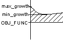
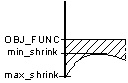
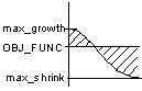
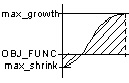
MASTER
Selected Master Displacement Value
MAX
max_growth
min_shrink
max_growth
max_growth
MIN
min_growth
max_shrink
max_shrink
max_shrink
- The CLIENT specification determines the displacement of the client nodes from the Master_Node of the optimization displacement.
- CLIENT = PLANE_SYM: The surface which lies normal to the specified axis is a symmetrical surface. The nodes (allocated via DVCON_SHAPE operator ND_GROUP) are checked against each other for their symmetry and symmetrical surfaces. Symmetrical nodes are combined to a symmetrical group (2 symmetrical nodes per symmetrical group is the norm). The master node of the symmetrical group is then determined and the displacement of the client node is calculated so it displaces in a surface symmetrical fashion to the master node.
- CLIENT = POINT_SYM: The point defined by the origin of the coordinate system CS is called the symmetrical point. The nodes (allocated via DVCON_SHAPE operator ND_GROUP) are checked against each other for their symmetry with reference to the symmetrical point. Symmetrical nodes are combined to a symmetrical group (2 symmetrical nodes per symmetrical group is the norm). The master node of the symmetrical group is then determined and the displacement of the client node is calculated so it displaces point symmetrical to the master node. For both symmetrical couplings the given coordinate system in the operator CS must be Cartesian (rectangular). The operator MASTER must have MAX or MIN.
- CLIENT = ROTATION_SYM: The specified axis defines the rotation axis of the surface of revolution. The nodes (allocated via DVCON_SHAPE operator ND_GROUP) are checked for their symmetry in the given rotation axis. All nodes at the same parallel of the surface of revolution are combined to a symmetrical group. The master node of the symmetrical group is then determined and the displacement of the client node is calculated so it displaces in a surface symmetrical fashion to the master node.
- CLIENT = VECTOR: Referring to the coordinate system entered in the operator CS, the difference between the current coordinates and the start coordinates of the master nodes is calculated. With reference to the coordinate system the start coordinates of the client nodes are then calculated, the difference in the master nodes are determined and the current coordinates of the client nodes are calculated. With VECTOR=ON/OFF, ON/OFF, ON/OFF these coordinates are activated and transferred. The coordinates deactivated remain unchanged.
- CLIENT = DIRECTION: The procedure is similar to that of CLIENT = VECTOR with coupling of all three coordinates. The difference is that the obtained displacement vector is scaled to the original absolute value of the displacement of the client node.
- CLIENT = LENGTH: The absolute value of displacement of the master nodes is calculated. The displacement of the client nodes is scaled so the absolute value of the obtained displacement of the master node remains.
- CLIENT = DISP_CS: The optimization displacement of the master nodes based upon the FE displacement coordinate system is transferred directly in the FE displacement coordinate system of the client nodes. The coupled FE displacement coordinate systems must be of the same kind, i.e. either Cartesian, cylindrical or spherical. With DISP_CS=ON/OFF, ON/OFF, ON/OFF these coordinates that are activated are transferred. The coordinates deactivated remain unchanged.
- CLIENT = SURF_PLANE_SYM: The nodes are checked to be symmetric with respect to the given symmetry plane in symmetric but non-symmetric meshed models. The node corrections are applied in node normal direction only.
- CLIENT = SURF_CYCLIC_SYM: Couples nodes in a not necessary symmetric mesh that reoccur in a cyclic manner around a rotational axis.
- CLIENT = SURF_CYCLIC_PLANE_SYM: Combination of SURF_CYCLIC_SYM and SURF_PLANE_SYM. Nodes are first coupled in a cyclic manner and then plane symmetry is enforced within each cyclic section. The position of the plane symmetric sections is controlled with the CYCLIC_SYM_START parameter.
- CLIENT = SURF_STAMP: The nodes are linked to keep a stampable surface. Master nodes are determined automatically.
- CLIENT = SURF_TURN: The nodes are linked to keep a turnable surface. Master nodes are determined automatically.
- CLIENT = SURF_DRILL: The nodes are linked to keep a turnable surface. Master nodes are determined automatically. The drill restriction is a special combination of the turn and demold restriction.
- CLIENT = SURF_DEMOLD: The nodes are linked to keep a castable surface.
- The CLIENTs PLANE_SYM, ROTATION_SYM, SURF_STAMP, SURF_TURN, SURF_DRILL, SURF_DEMOLD, SURF_CYCLIC_SYM, SURF_PLANE_SYM, SURF_CYCLIC_PLANE_SYM can be used without the AXIS_* parameter. Thus, an arbitrary axis direction <x,y,z> can be specified with reference to CS with the entry CLIENT_DIR = x,y,z. For SURF_STAMP an additional demolding direction can be defined using the DEMOLD_DIR parameter, also available for the definition of the demolding direction for SURF_DEMOLD.
- CS: Name of the coordinate system that operates LINK_SHAPE. Specifying the coordinate system is essential for CLIENT=PLANE_SYM, POINT_SYM, ROTATION_SYM, VECTOR, DIRECTION, SURF_STAMP, SURF_TURN, SURF_DRILL, SURF_DEMOLD, SURF_CYCLIC_SYM, SURF_PLANE_SYM or SURF_CYCLIC_PLANE_SYM. Specifying the coordinate system for CLIENT=LENGTH or DISP_CS is unnecessary. With CLIENT=PLANE_SYM and POINT_SYM only Cartesian coordinate systems are permitted.
- TOL: Specifying the tolerance values for CLIENT=PLANE_SYM, POINT_SYM, ROTATION_SYM or SURF_DEMOLD is essential. Specifying the tolerance values for CLIENT=VECTOR, DIRECTION, LENGTH, DISP_CS, SURF_STAMP, SURF_TURN, SURF_DRILL, SURF_CYCLIC_SYM, SURF_PLANE_SYM or SURF_CYCLIC_PLANE_SYM is unnecessary. The tolerance values must be positive. At least one of three tolerance values must be entered. For tolerance values not given, the smallest of the given tolerance values is acceptable. The three tolerance values are also coordinate values referring to the three coordinate directions of the CS. The values of tolerance should be large enough to cover the individual nodes and small enough not to cover any not wanted neighboring nodes.
- The parameter SURF_PARAM = <master_areas>, <net_points> is used to create a spline that defines the "surface" in the allowed LINK_SHAPE commands. The values <master_areas>, <net_points> are integer values and automatically determined by SIMULIA Tosca Structure. In the event of an error it may help setting SURF_PARAM. Important is that <master_areas> must be larger than 4 and at least double the size of <net_points>. Good values are e.g. SURF_PARAM = 12, 4. For more information, see Remarks at .
![]()
Examples
LINK_SHAPE
 ID_NAME = my_link_01
 MASTER = MAX
 CLIENT = PLANE_SYM, AXIS_3
 CS = cs_0
 TOL = 0.01, 0.01, 0.01
END_
LINK_SHAPE
 ID_NAME = DEMOLD_AREA
 MASTER = MAX
 CLIENT = SURF_DEMOLD, AXIS_2
 CS = cs_0
 ANGLE = 1.5
 TOL = 0.01, 0.01, 0.01
 CHECK_GROUP = CHK_NDGRP_DEMOLD
END_