| CLIENT / Applicable for |
Controller (SHAPE_CONTROLLER) |
Sensitivity (SHAPE_SENSITIVITY) |
| PLANE_SYM |
OK |
- |
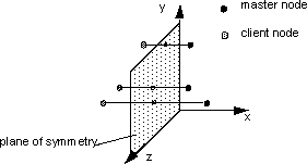
To be able to couple displacements symmetric to a plane, the position
and the orientation of the plane must be exactly specified. It is also
necessary to specify tolerances in order to identify symmetric nodes.
The following four parameters are necessary for the definition of the
link condition:
        CLIENT = PLANE_SYM
        CLIENT_DIR = <X_1>, <X_2>, <X_3>
        CS = name_of_coord_system
        TOL = <tol_1>, <tol_2>, <tol_3>
The origin of the coordinate system referenced by CS defines a point on
the plane. The direction specified by the CLIENT_DIR
parameter defines the normal of the plane. The symmetry of the nodes
(assigned by ND_GROUP in the DVCON_SHAPE
command) is checked against the symmetry plane. Symmetric nodes are
assembled into a symmetry group (normally two symmetric nodes per symmetry
group). Then the master node of the symmetry group is determined and
the displacements of the client nodes are calculated in such a way that
they move symmetrically to the plane of the master node (see the following
figure).
The tolerances are required in order to identify symmetric nodes. Symmetric nodes share equal coordinates in
the plane and inversely equal coordinates normal to the plane (and added
tolerances). The three tolerance values tol_* are assigned to the three
coordinate directions of the coordinate system referenced by CS.