Stampable, turnable and drillable surfaces | ||||||
|
| |||||
| CLIENT / Applicable for | Controller (SHAPE_CONTROLLER) | Sensitivity (SHAPE_SENSITIVITY) |
|---|---|---|
| SURF_STAMP | OK | - |
| SURF_TURN | OK | - |
| SURF_DRILL | OK | - |
Stampable surface (SURF_STAMP)
Maintaining a stampable surface during optimization involves defining a stamping direction. The stamping domain is defined using a node group. The direction defined by the CLIENT_DIR parameter specifies the stamping direction.The link condition is defined using the following parameters:
          CLIENT = SURF_STAMP
          CLIENT_DIR = <x_1>,<x_2>,<x_3>
          CS = name_of_coord_system
The master nodes are found using the standard master criterion. The stamping surface is defined using the given stamping direction and the cutting edge automatically generated by SIMULIA Tosca Structure. All nodes of the node group are linked to this surface.
An additional demolding direction can be included:
DEMOLD_DIR = <x_1>,<x_2>,<x_3>
The demolding direction has to be orthogonal to the client direction. Therefore SIMULIA Tosca Structure projects the demold vector onto a plane normal to the client direction.
Important:
|
![]()
Turnable surface (SURF_TURN)
Maintaining a turnable surface during optimization involves defining a rotation axis. The domain that assures a turnable surface is defined using a node group, i.e. all nodes of the specified surface node group are checked for rotation symmetry in the given rotation axis. The link condition is defined using the following parameters:
          CLIENT = SURF_TURN
          CLIENT_DIR = <x_1>,<x_2>,<x_3>
          CS = name_of_coord_system
The direction defined by the CLIENT_DIR and the origin of the coordinate system specify the exact position and direction of the rotation axis.
The master nodes are found using the standard master criteria. The turning surface is defined using the given rotation axis and the cutting edge automatically generated by SIMULIA Tosca Structure. All nodes of the node group are linked to this surface.
Important:
|
![]()
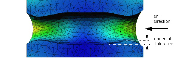
Drillable surface (SURF_DRILL)
The drill restriction is a combination of the turning and the demolding restriction. Maintaining a drillable surface during optimization involves defining the drill axis and the drill feed. The drilling domain is defined using a node group, i.e. all nodes of the specified surface node group are checked for drilling in the given drill direction. The link condition is defined using the following parameter:
          CLIENT = SURF_DRILL
          CLIENT_DIR = <x_1>,<x_2>,<x_3>
          CS = name_of_coord_system
          ANGLE = <real> (0° < angle < 45°)
The direction defined by the CLIENT_DIR and the origin of the coordinate system specify the exact position and direction of the drill axis, the angle specifies a minimum surface angle.
The shape of the drilling surface can be specified with an additional undercut tolerance. The term 'drilling surface' in this case should be interpreted in a more general sense.
UNDERCUT_TOL = <real> (>0)
 |
Important:
|