What can I do with the Virtual Topology toolset? | ||
| ||
- Combine faces or edges
You can select two or more faces or edges that Abaqus/CAE will combine into a single virtual face or virtual edge. If you combine two faces, any edges between the faces are ignored when Abaqus generates the mesh. Similarly, if you combine two edges, any vertices between the edges are ignored when the mesh is generated.
- Ignore an edge or a vertex
You can select edges or vertices that Abaqus/CAE will ignore. Ignoring an edge between two faces is the equivalent of combining the faces. Similarly, ignoring a vertex between two edges is the equivalent of combining the edges; however, you will find the combine tools useful when you have a large number of faces and edges to combine. Using ignore to create virtual topology has the same effect as using combine to create virtual topology—ignored edges or vertices are not considered when Abaqus generates the mesh.
- Automatically combine or ignore entities
You can specify a set of geometric parameters that Abaqus/CAE will use to create virtual topology. You can also select the area—faces, parts, part instances, or an entire assembly—to which Abaqus/CAE will apply the selected parameters. The virtual topology parameters are located in the Create Virtual Topology dialog box, which also includes tools that you can use to measure and highlight entities and preview the virtual topology. When you are finished, Abaqus/CAE creates a single virtual topology feature that contains all of the changes.
- Restore entities
Rather than deleting or suppressing virtual topology features that may contain entities that you want to ignore along with some that you need to use, you can use the Restore Entities tool to highlight all entities that have been ignored and select the ones that you want to reactivate.
To preserve mesh quality, edges and faces to be combined should have shallow included angles that are close to 180°. The recommended angle is between 120° and 240°. You can use the angle method to choose only adjacent faces with shallow included angles. For more information, see Using the angle and feature edge method to select multiple objects. If the included angle at some edges or vertices lies outside this range, Abaqus/CAE displays a warning and allows you to remove those edges or vertices from your selection. If you choose to retain the sharp edges, the resulting mesh may not lie on a smooth surface. Figure 1 illustrates a mesh on a virtual surface that is not smooth.

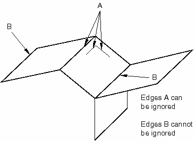
You can ignore an edge only if that edge is shared by two adjacent faces or if it is embedded in a face. For example, you cannot ignore the free edge of a shell or an edge shared by three faces, as shown in Figure 2.
Similarly, you can ignore a vertex only if that vertex is shared by two adjacent edges or embedded in a face. For example, you cannot ignore the vertex at the free end of a wire or where a wire intersects with a face, as shown in Figure 3.

Abaqus/CAE does not support all of the meshing techniques on regions that contain virtual topology (combined faces or combined edges). Specifically, Abaqus/CAE does not support the following:
Two-dimensional free meshing with quadrilateral or quadrilateral-dominated elements using the medial axis algorithm.
Three-dimensional swept meshing using the medial axis algorithm.
Two-dimensional structured meshing if the region to be meshed is not bounded by four corners.
Three-dimensional structured meshing if the region to be meshed is not bounded by six sides.
If you need to apply virtual topology to a dependent instance, you can create a copy of the original part and then create an independent instance of the copy. You can then replace the dependent instance with the new independent instance and apply virtual topology to the replacement. For more information, see What is the difference between a dependent and an independent part instance?.
You may be able to make a part swept meshable by combining multiple faces on the target side into a single face; for more information, see Swept meshing of three-dimensional solids. However, if you combine many faces into a single face, the meshing procedure may be slower and the resulting mesh may not be acceptable. If you try to combine a large number of faces into a single face, Abaqus/CAE displays a warning and allows you to change your selection. Abaqus/CAE calculates the number of faces being combined from the cumulative number of faces in your selection. For example, if you try to combine two faces each of which already contains five combined faces, the cumulative number of faces will be ten.