Swept meshing of three-dimensional solids | ||
| ||
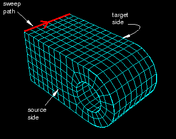
If a region is swept meshable, Abaqus/CAE can generate the swept mesh on a region that has been assigned the Hex, Hex-dominated, or Wedge element shape option. To generate the preliminary two-dimensional mesh on the source side, Abaqus/CAE uses the free meshing technique with the Quad, Quad-dominated, or Tri element shape option, respectively.
You can choose between the medial axis and advancing front meshing algorithms when you mesh a solid region with hexahedral or hexahedral-dominated elements using the swept meshing technique. (Abaqus/CAE generates hexahedral and hexahedral-dominated meshes by sweeping the quadrilateral and quadrilateral-dominated elements generated by the two algorithms from the source side to the target side.) However, if the region to be meshed contains virtual topology, you can use only the advancing front algorithm to generate the swept mesh. For more information, see What is the difference between the medial axis algorithm and the advancing front algorithm?, and Free meshing with quadrilateral and quadrilateral-dominated elements.
If you select the advancing front algorithm, Abaqus/CAE will use mapped meshing, if it is appropriate, to improve the mesh for some regions. (Mapped meshing is the same as structured meshing but applies only to four-sided regions.) Abaqus/CAE determines whether it is appropriate to replace the advancing front algorithm with mapped meshing on any of the faces that belong to the source side. For more information, see What is mapped meshing?, and When can Abaqus/CAE apply mapped meshing?. Abaqus/CAE uses mapped meshing to create quadrilateral and quadrilateral-dominated elements on these appropriate boundary faces and then sweeps the elements from the source side to the target side to create the hexahedral and hexahedral-dominated elements.
A three-dimensional region can be meshed using the swept meshing technique if it has the following characteristics:
Every side that connects the source side to the target side must have only a single face or be comprised of four-sided combined faces that form a regular grid pattern. Figure 3 provides two examples of acceptable connecting face patterns.
Figure 3. Acceptable connecting face patterns for swept meshing.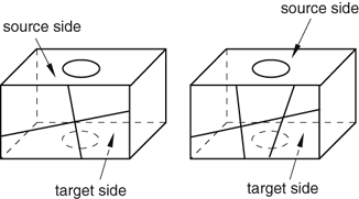
The partitioned connecting sides in Figure 4 do not have acceptable face patterns for swept meshing; the model on the left side has a sweep face with two three-sided faces, while the model on the right side does not have a regular grid pattern.
Figure 4. Unacceptable connecting face patterns for swept meshing.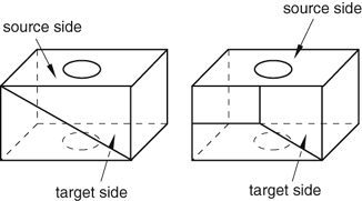
The target side must contain only a single face without isolated edges or isolated vertices. For example, the region on the left in Figure 5 can be meshed using the swept meshing technique because all of the isolated edges are on the source side; the region on the right, however, cannot be meshed using this technique because the target side contains two faces.
Figure 5. Only the region on the left can be meshed using the swept meshing technique.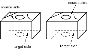
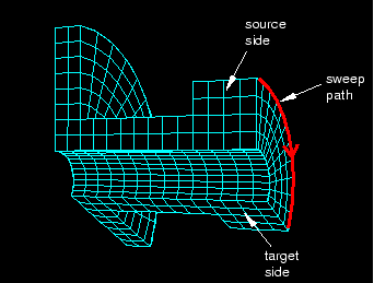
Figure 6 illustrates a part that has been swept meshed along a varying cross-section. The part appears to be relatively complex; for example, the source side is nonplanar, and the cross-section of the part varies along the sweep path. However, the rules for generating a swept mesh still apply.
Every side that connects the source side to the target side contains only a single face.
Although the source side contains two faces, the target side contains only a single face.
Figure 6. Sweeping the mesh along a varying cross-section.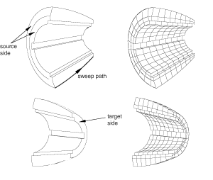
You may be able to use virtual topology to combine faces on the target side to make a part swept meshable. Figure 7 illustrates a part that was swept mesh after the five faces on the target side were combined into a single face using virtual topology. However, because the part now contains virtual topology, it can be swept meshed with only the advancing front algorithm.
Figure 7. Combining faces makes a part swept meshable.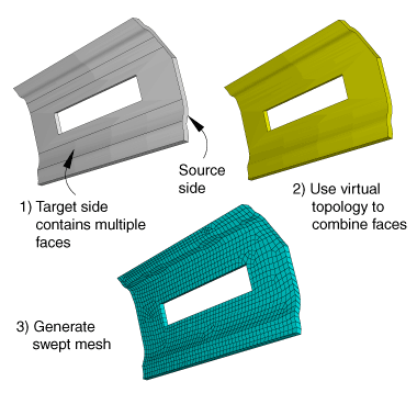
For a revolved region, the profile that was revolved to create the region must not touch the axis of revolution at one or more isolated points, as shown in Figure 8.
Figure 8. The swept meshing technique cannot mesh a part if an isolated point touches the axis of revolution.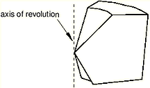
Similarly, Abaqus/CAE cannot mesh a region with hexahedral or wedge elements if one or more edges lie along the axis of revolution, as shown in Figure 9.
Figure 9. Abaqus/CAE cannot mesh a region with hexahedral elements if one or more edges lie along the axis of revolution.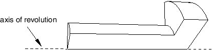
However, Abaqus/CAE can mesh the region with hexahedral-dominated elements by generating layers of wedge elements along the axis, as shown in Figure 10.
Figure 10. Abaqus/CAE can mesh the region with hexahedral-dominated elements.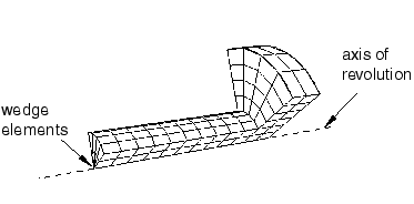
As a result, you must select the Hex-dominated element shape option before you mesh the region. Alternatively, you can partition the region into simple structural mesh regions and select the Hex element shape option to create the mesh using all hexahedral elements. For more information, see Sweep meshing a solid, revolved region whose profile touches the axis of revolution.
A fully revolved region that does not touch the axis of revolution is meshable only if all the edges that are associated with the profile being revolved exist. However, the edges that bound the profile must not create a face. Figure 11 shows a meshable part instance where all of the edges of the revolved profile exist.
Figure 11. All of the edges of the revolved profile exist; hence, the part instance is meshable.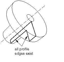
In this example the user sketched the profile, and Abaqus/CAE revolved the profile to create the part; however, the edges that bound the profile do not form a face. In contrast, Figure 12 shows a part instance that is not meshable because some of the edges of the revolved profile are missing.
Figure 12. Some of the edges of the revolved profile are missing; hence, the part instance is not meshable.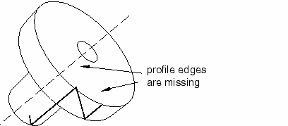
A fully revolved region that touches the axis of revolution is meshable only if all of the edges that are associated with the profile being revolved exist except the edges along the axis of revolution. Figure 13 shows a part instance that is meshable because all of the edges of the revolved profile exist except for the edge along the axis of revolution. If the profile included the edge along the axis of revolution, the part instance would not be meshable.
Figure 13. All of the edges of the revolved profile exist, except for the edge along the axis of revolution; hence, the part instance is meshable.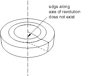
If a revolved region was created by revolving a sketch that contains a spline, the region is meshable only if the vertices at each end of the spline are not on the axis of revolution.
If a part was created by sweeping a cross-section along a sweep path that is composed of a closed spline, the resulting part is meshable only if it is split into two or more regions.