What is the difference between the medial axis algorithm and the advancing front algorithm? | ||||
|
| |||
Meshing a surface with quadrilateral or quadrilateral-dominated elements using the free meshing technique.
Meshing a solid region with hexahedral or hexahedral-dominated elements using the swept meshing technique. (Abaqus/CAE generates hexahedral and hexahedral-dominated meshes by sweeping the quadrilateral and quadrilateral-dominated elements generated by the two algorithms from the source side to the target side.)
The two algorithms are described as follows:
- Medial axis
The medial axis algorithm first decomposes the region to be meshed into a group of simpler regions. The algorithm then uses structured meshing techniques to fill each simple region with elements. If the region being meshed is relatively simple and contains a large number of elements, the medial axis algorithm generates a mesh faster than the advancing front algorithm. Minimizing the mesh transition may improve the mesh quality. The mesh transition option is available only for quadrilateral and hexahedral meshing. For more information, see What is a mesh transition?.
- Advancing front
The advancing front algorithm generates quadrilateral elements at the boundary of the region and continues to generate quadrilateral elements as it moves systematically to the interior of the region.
The elements generated by the advancing front algorithm will always follow the seeding exactly for quadrilateral-dominated and hexahedral-dominated meshes (except when you are creating a three-dimensional revolved mesh, and the profile being revolved touches the axis of revolution). For other meshes the elements generated by the advancing front algorithm will always follow the seeding more closely than those generated by the medial axis algorithm. If the region to be meshed contains virtual topology, you can use only the advancing front algorithm to generate the mesh.
If you select the advancing front algorithm, you can allow Abaqus/CAE to use mapped meshing where appropriate. (Mapped meshing is the same as structured meshing but applies to only four-sided regions.) For more information, see What is mapped meshing?, and When can Abaqus/CAE apply mapped meshing?.
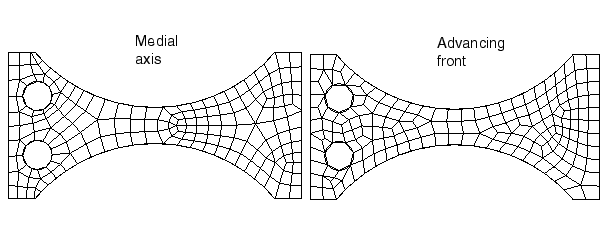
You may have to experiment with the two algorithms to obtain the optimal mesh. Figure 1 illustrates a simple shell region that was meshed with quadrilateral-dominated elements using the two meshing algorithms. In this example both algorithms generate an acceptable mesh.

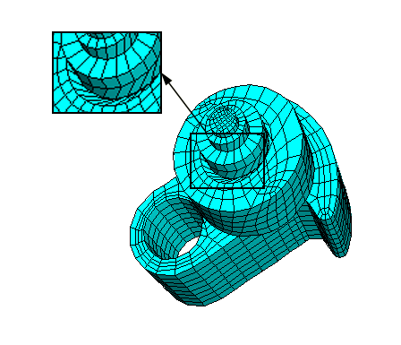
Because the elements produced by the advancing front algorithm follow your seeds, the resulting mesh may include some skew in the elements in narrow regions. Element skew is illustrated in Figure 2.

In contrast, the advancing front algorithm may generate elements of a more uniform size with a more consistent aspect ratio, as shown in Figure 3. Uniform element size can play an important role in the analysis; for example, if you are creating a mesh for an Abaqus/Explicit analysis, small elements in the mesh can unduly control the size of the time step. In addition, if it is important that the elements follow your seeds, the advancing front algorithm is preferable.

In some cases, when you mesh multiple regions, Abaqus/CAE generates a mesh with sheared elements at the interface between regions. Nodes in one region may be positioned differently than nodes in an adjacent region, which results in shear at the common boundary when Abaqus/CAE merges the adjacent meshes. Figure 4 shows multiple swept regions and the resulting mesh generated by the medial axis algorithm.

The advancing front algorithm positions the nodes on the source side at the same location as your seeds; as a result, the mesh shear will be reduced. Figure 5 shows the same part meshed with the same seeding using the advancing front algorithm. However, as stated earlier, you may have to experiment with the two algorithms to obtain the optimal mesh.
