Sweep meshing a solid, revolved region whose profile touches the axis of revolution | ||
| ||
Context:
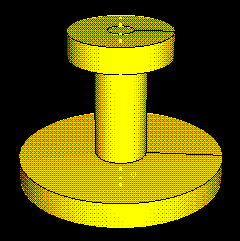
In most cases, unless you create strategically placed partitions, you cannot
sweep mesh a revolved solid region with all hexahedral elements if the profile
that was revolved to create the region touches the axis of revolution. For
example, the cylindrical part in the following figure cannot be swept meshed.

The partitioning technique to make the part swept meshable involves dividing the part or part instance into the following two regions:
-
A cylindrical core region that can be meshed using the extruded swept meshing technique.
-
An outer region that can be meshed using the revolved swept meshing technique.
(For detailed information on sweep meshing solid regions, see Swept meshing of three-dimensional solids.)
| Tip: The following instructions refer to color cues that appear only when the Mesh defaults color mapping is selected. Apply this color mapping to your viewport before attempting to partition a solid, revolved region for sweep meshing. |
Use the Partition toolset to create a cylindrical core at the center of the region. (For detailed information on partitions, see The Partition toolset.”) The partitions creating the cylindrical core are outlined in red in the figure below.
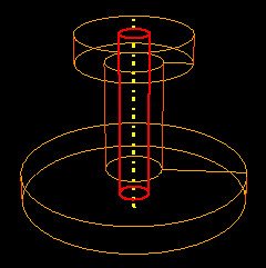
The cylindrical core is meshable using the extruded swept meshing technique and therefore becomes yellow. The outer region remains orange because it is still unmeshable.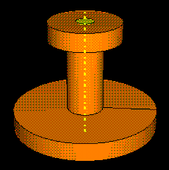
In the next step you will create additional partitions that allow Abaqus/CAE to recognize the outer region as a revolved solid whose profile does not touch the axis of revolution.Use the Partition toolset to create whatever partitions are necessary to outline a revolution profile for the outer region. The profile will serve as the source side of the revolved mesh and will be swept along the circular edge defined by the cylindrical core to create the solid mesh.
For example, partitions are used to outline the profile (shown in red) of the outer region in the figure below.
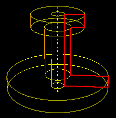
Once the profile has been defined, both the cylindrical inner region and the outer region are colored yellow and are ready for sweep meshing.
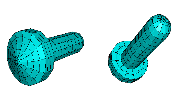
The resulting mesh is shown below.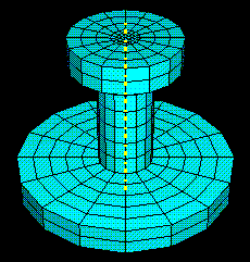
You can apply a similar technique to mesh revolved regions even though the source side and the target side are not planar, as shown below.