Components of the toolbars | ||||
|
| |||
The toolbars are shown in the following figure:
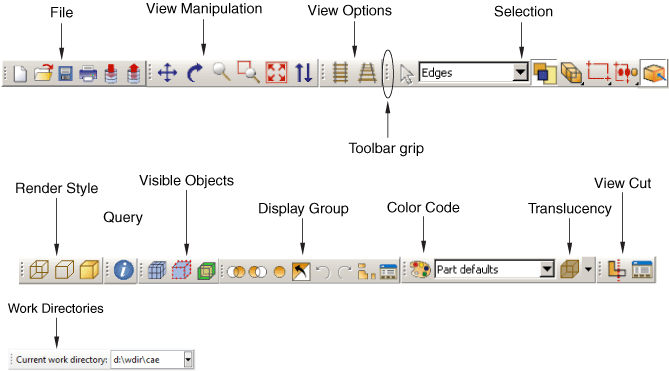
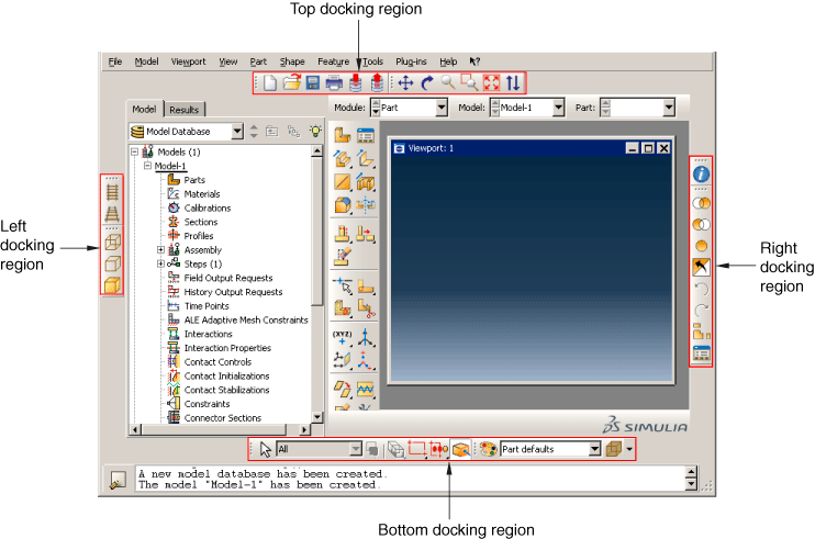
You can change the location of a toolbar using the toolbar's grip, as indicated in the above figure. Clicking and dragging the grip moves the toolbar around the main window. If you release the toolbar grip while the toolbar is over one of the four available docking regions of the main window (see Figure 1), Abaqus/CAE “docks” the toolbar; a docked toolbar has no title bar and does not obstruct any other portion of the main window.
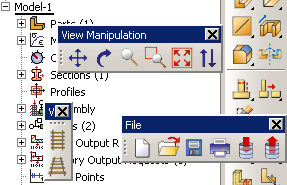
If you release the toolbar grip while the toolbar is not near a docking region, Abaqus/CAE creates a floating toolbar with a title bar. A floating toolbar obstructs other items in the main window (see Figure 2); however, a floating toolbar can be positioned outside of the Abaqus/CAE main window.
Clicking mouse button 3 on a toolbar grip displays a menu that lets you specify the location and format of the toolbar:
-
Select to dock the toolbar in the top docking region.
-
Select to dock the toolbar in the bottom docking region.
-
Select to dock the toolbar in the left docking region.
-
Select to dock the toolbar in the right docking region.
-
Select to change a docked toolbar into a floating toolbar; this option is available only for docked toolbars.
-
Select to change the orientation of a floating toolbar from horizontal to vertical, or vice versa; this option is available only for floating toolbars.
You can also hide toolbars and create custom toolbars that include shortcuts to additional functions. For more information, see The Customize toolset.
To obtain a short description of a tool in a toolbar, place the cursor over that tool for a moment; a small box containing a description, or “tooltip,” will appear. To obtain the name of a toolbar, place the cursor over the toolbar grip for a moment.
The Abaqus/CAE toolbars contain the following functionality:
- File
-
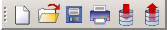
The File toolbar allows you to create, open, and save model databases; to open output databases; to print viewports; and to save and load session objects and options. For more information, see Working with Abaqus/CAE Model Databases, Models, and Files; Printing viewports; and Managing session objects and session options.
- Work Directories
-
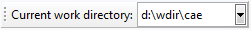
The Work Directories toolbar allows you to change the current working directory. The list provided in the toolbar contains the five most recently used work directories. For more information, see Setting the work directory.
- Viewport
-

The Viewport toolbar allows you to create and align viewports, link viewports, and create viewport annotations. For more information, see Managing viewports and viewport annotations from the Viewport toolbar. The Viewport toolbar is not displayed by default.
- View Manipulation
-

The View Manipulation toolbar allows you to specify different views of the model or plot. For example, you can pan, rotate, or zoom the model or plot using these tools. For more information, see Manipulating the view and controlling perspective.
- View Options
-

The View Options toolbar allows you to specify whether or not perspective is applied to your model. For more information, see Controlling perspective.
- Views
-

The Views toolbar allows you to apply a custom view to the model in the viewport. For more information, see Custom views. The Views toolbar is not displayed by default.
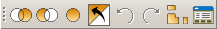
- Render Style
-

The Render Style toolbar allows you to specify whether the wireframe, hidden line, or shaded render style will be used to display your model. In the Visualization module the Render Style toolbar also includes the filled render style
 tool. For more information, see
Choosing a render style.
tool. For more information, see
Choosing a render style.
- Visible Objects
-

The Visible Objects toolbar allows you to switch between displaying the geometry of an Abaqus/CAE native part and the meshed representation of the same part, to toggle the display of seeds on and off, and to toggle the display of the reference representation on or off if the meshed representation and reference representation exist. For more information, see Displaying a native mesh, What are mesh seeds?, and Understanding the reference representation.
- Selection
-
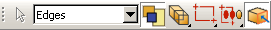
The Selection toolbar allows you to enable or disable object selection by toggling on the arrow icon. You can use the list to the right of the arrow to limit the types of objects that you can select. The Selection toolbar is available only when there are no active procedures running in a viewport. For more information, see Selecting objects before choosing a procedure.
- Query
-

The Query toolbar allows you to obtain information about the geometry and features of your model, to probe model and X–Y plots for output data, and to perform stress linearization on your results. For more information, see The Query toolset; Probing the model; and Calculating linearized stresses.
- Display Group
-
The Display Group toolbar allows you to selectively plot one or more model or output database items. For example, you can create a display group that contains only the elements belonging to specified sets in your model. For more information, see Using display groups to display subsets of your model.
- Color Code
-
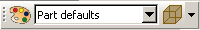
The Color Code toolbar allows you to customize the colors of items in the viewport and change the degree of their translucency.
For color coding, you can create color mappings that assign unique colors to different elements of a display. For example, when using a part instance color mapping, each part instance in a model will appear as a different color. For more information, see Color coding geometry and mesh elements.
For translucency, you can click the arrow to the right of the
 tool to reveal a slider, which you can drag to make the display
colors more transparent or more opaque. For more information, see
Changing the translucency.
tool to reveal a slider, which you can drag to make the display
colors more transparent or more opaque. For more information, see
Changing the translucency.
- View Cut
-

The View Cut toolbar allows you to toggle the display of view cuts in modules other than the Visualization module and to customize their definition and display. For more information, see Cutting through a model. The View Cut toolbar is displayed by default; in the Visualization module, view cut options are available in the toolbox.
- Field Output
-

The Field Output toolbar allows you to control two aspects of field output variable display:
-
You can select the field output variable that you want to display in the current viewport. Selections include the type of field output variable (Primary, Deformed, or Symbol), the variable name, and if available, the invariants and components for the selected primary variable.
-
For changes in variable type, you can control whether Abaqus/CAE automatically synchronizes the plot state in the current viewport with the new selection of variable type. If the
 tool is toggled on,
Abaqus/CAE
synchronizes the plot state if the newly selected field output variable
requires a change in plot state; if this option is toggled off, Abaqus/CAE
still updates the output variable displayed in the viewport but does not change
the plot state in the current viewport.
tool is toggled on,
Abaqus/CAE
synchronizes the plot state if the newly selected field output variable
requires a change in plot state; if this option is toggled off, Abaqus/CAE
still updates the output variable displayed in the viewport but does not change
the plot state in the current viewport.
The selections in the toolbar are limited, but the
 tool provides access to the Field Output dialog
box, if needed. For more information about the options in the toolbar, see
Using the field output toolbar.
tool provides access to the Field Output dialog
box, if needed. For more information about the options in the toolbar, see
Using the field output toolbar.
-