An inelastic constitutive model for concrete | ||||||
|
| |||||
ProductsAbaqus/Standard
The material library in Abaqus also includes a constitutive model for concrete based on theories of scalar plastic damage, described in Damaged plasticity model for concrete and other quasi-brittle materials, which is available both in Abaqus/Standard and Abaqus/Explicit. In Abaqus/Explicit plain concrete can also be analyzed with the cracking model described in A cracking model for concrete and other brittle materials. It is intended that reinforced concrete modeling be accomplished by combining standard elements, using this plain concrete model, with “rebar elements”—rods, defined singly or embedded in oriented surfaces, that use a one-dimensional strain theory and that may be used to model the reinforcing itself.
These elements are superposed on the mesh of plain concrete elements and are used with standard metal plasticity models that describe the behavior of the rebar material. This modeling approach allows the concrete behavior to be considered independently of the rebar, so this section discusses the plain concrete model only. Effects associated with the rebar/concrete interface, such as bond slip and dowel action, cannot be considered in this approach, except by modifying some aspects of the plain concrete behavior to mimic them, such as the use of “tension stiffening” to simulate load transfer across cracks through the rebar.
The theory described in this section is intended as a model of concrete behavior for relatively monotonic loadings under fairly low confining pressures (less than four to five times the largest compressive stress that can be carried by the concrete in uniaxial compression). Cracking is assumed to be the most important aspect of the behavior, and it dominates the modeling. Cracking is assumed to occur when the stresses reach a failure surface, which we call the “crack detection surface.” This failure surface is taken to be a simple Coulomb line written in terms of the first and second stress invariants, p and q, that are defined below. The anisotropy introduced by cracking is assumed to be important in the simulations for which the model is intended, so the model includes consideration of this anisotropy. The model is a smeared crack model, in the sense that it does not track individual “macro” cracks: rather, constitutive calculations are performed independently at each integration point of the finite element model, and the presence of cracks enters into these calculations by the way the cracks affect the stress and material stiffness associated with the integration point. Various objections have been raised against such smeared crack models. The principal concern is that this modeling approach inherently introduces mesh sensitivity in the solutions, in the sense that the finite element results do not converge to a unique result. For example, since cracking is associated with strain softening, mesh refinement will lead to narrower crack bands. Crisfield (1986) discusses this concern in detail and concludes that Hillerborg's (1976) approach, based on brittle fracture concepts, is adequate to deal with this issue for practical purposes. This aspect of the model is discussed below in the section on cracking. For simplicity of discussion in what follows, the term “crack” is used to mean a direction in which cracking has been detected at the single constitutive calculation point in question: the closest physical concept is that there exists a continuum of micro-cracks at the point, oriented as determined by the model.
When the principal stress components are dominantly compressive, the response of the concrete is modeled by an elastic-plastic theory, using a simple form of yield surface written in terms of the first two stress invariants. Associated flow and isotropic hardening are used. This model significantly simplifies the actual behavior: the associated flow assumption generally overpredicts the inelastic volume strain; the simple yield surface used does not match all data very accurately (the third stress invariant would be needed to improve this aspect of the model); and, especially when the concrete is strained beyond the ultimate stress point, the assumption of constant elastic stiffness does not reproduce the observation that the unloading response is significantly weakened (the elastic response of the material appears to be damaged). In addition, when concrete is subjected to very high pressure stress, it exhibits inelastic response: no attempt has been made to build this behavior into the model. In spite of these limitations the model provides useful predictions for a variety of problems involving inelastic loading of concrete. The limitations are introduced for the sake of computational efficiency. In particular, assuming associated flow leads to enough symmetry in the Jacobian matrix of the constitutive model (the “material stiffness matrix”) that the overall equilibrium equation solution usually does not require nonsymmetric equation solution for this reason. All of these limitations could be removed at some sacrifice in computational cost.
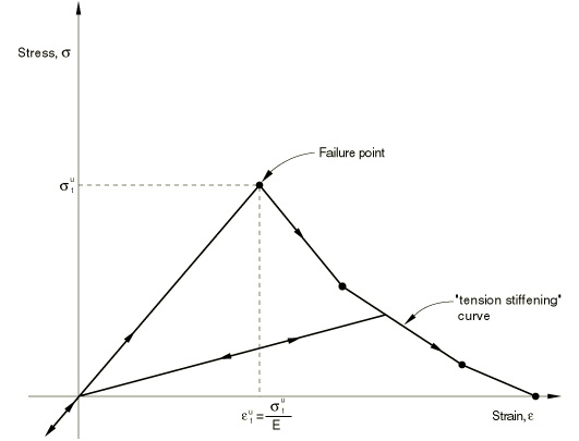
The cracking and compression responses of concrete that are incorporated in the model are illustrated by the uniaxial response of a specimen shown in Figure 1.
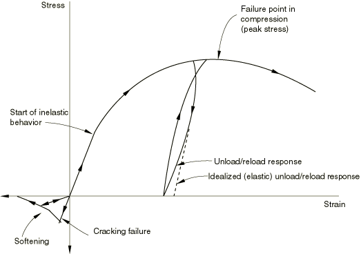
When concrete is loaded in compression, it initially exhibits elastic response. As the stress is increased, some nonrecoverable (inelastic) straining occurs, and the response of the material softens. An ultimate stress is reached, after which the material softens until it can no longer carry any stress. If the load is removed at some point after inelastic straining has occurred, the unloading response is softer than the initial elastic response: this effect is ignored in the model. When a uniaxial specimen is loaded into tension, it responds elastically until, at a stress that is typically 7–10% of the ultimate compressive stress, cracks form so quickly that—even on the stiffest testing machines available—it is very difficult to observe the actual behavior. For the purpose of developing the model, we assume that the material loses strength through a softening mechanism and that this is dominantly a damage effect, in the sense that open cracks can be represented by loss of elastic stiffness (as distinct from the nonrecoverable straining that is associated with classical plasticity effects, such as what we are using for the compressive behavior model). The model neglects any permanent strain associated with cracking; that is, we assume that the cracks can close completely when the stress across them becomes compressive.
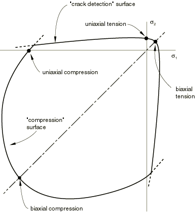
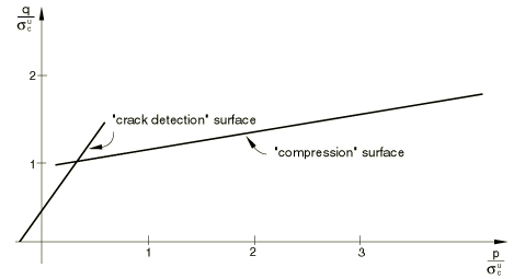
In multiaxial stress states these observations can be generalized through the concept of surfaces of failure and of ultimate strength in stress space. These surfaces are defined below and are fitted to experimental data. Typical surfaces are shown in Figure 2 and Figure 3.
This model makes no attempt to include prediction of cyclic response or of the reduction in the elastic stiffness caused by inelastic straining because the model is intended for application to relatively monotonic loading cases. Nevertheless, it is likely that—even in such cases—the stress trajectories will not be entirely radial and the model must predict the response in such cases in a reasonable way. An isotropically hardening “compressive” yield surface forms the basis of the model for the inelastic response when the principal stresses are dominantly compressive. In tension once cracking is defined to occur (by the “crack detection surface” of the model), the orientation of the cracks is stored and oriented, damaged elasticity is then used to model the existing cracks. Stress components associated with an open crack are not included in the definition of the crack detection surface for detecting additional cracks at the same point, and we only allow cracks to form in orthogonal directions at a point.
Since Abaqus/Standard is an implicit, stiffness method code and the material calculations used to define the behavior of the concrete are carried out independently at each integration point in that part of the model that is made of concrete, the solution is known at the start of the time increment. The constitutive calculations must provide values of stress and material stiffness at the end of the increment, based on the current estimate of the kinematic solution for the response at the spatial integration point during the increment that provides the (logarithmic) strain, , at the end of the increment.
Once cracks exist at a point, the component forms of all vector and tensor valued quantities are rotated so that they lie in the local system defined by the crack orientation vectors (the normals to the crack faces). The model ensures that these crack face normal vectors will be orthogonal, so that this local system is rectangular Cartesian. This use of a local system simplifies the computation of the damaged elasticity used for the components associated with existing cracks.
The model, thus, consists of a “compressive” yield/flow surface to model the concrete response in predominantly compressive states of stress, together with damaged elasticity to represent cracks that have occurred at a material calculation point, the occurrence of cracks being defined by a “crack detection” failure surface that is considered to be part of the elasticity. The details of this model are now presented.
Elastic-plastic model for concrete
The model uses the classical concepts of plasticity theory: a strain rate decomposition into elastic and inelastic strain rates, elasticity, yield, flow, and hardening.
![]()
Strain rate decomposition
We begin with a strain rate decomposition:
where is the total mechanical strain rate, is the elastic strain rate (which includes crack detection strains—this elastic strain will be further decomposed when we describe the elasticity), and is the plastic strain rate associated with the “compression” surface.
We assume that the elastic part of the strain is always small, so this equation can be integrated as
![]()
Compression yield
The “compression” surface is
where p is the effective pressure stress, defined as
and q is the Mises equivalent deviatoric stress:
where are the deviatoric stress components; is a constant, which is chosen from the ratio of the ultimate stress reached in biaxial compression to the ultimate stress reached in uniaxial compression; and is a hardening parameter ( is the size of the yield surface on the q-axis at , so that is the yield stress in a state of pure shear stress when all components of are zero except ). The hardening is measured by the value of : the relationship is user-specified.
This simple surface is a straight line in (p–q) space and provides a good match to experimental data over a fairly wide range of pressure stress values (up to four to five times the maximum compressive stress that can be carried by the concrete in uniaxial compression). This form of the surface means that, as the hardening () changes, the surfaces in (p–q) space are similar, so—for example—the ratio of flow stress in biaxial loading to flow stress in uniaxial loading is the same at all flow stress levels. This does not appear to be contradicted by any experimental data, and it means that only one constant () is needed to define the shape of the surface.
The value of is established from the user's data as follows. In uniaxial compression and , where is the stress magnitude. Therefore, on ,
In biaxial compression and , where is the magnitude of each nonzero principal stress. Therefore, on ,
The value of is specified by the user as part of the failure surface data (typically ). can be calculated from Equation 4 and Equation 5 as
The “compression” surface is shown in Figure 2 and Figure 3.
![]()
Hardening
The user defines the hardening by specifying the magnitude of the stress, , in a uniaxial compression test as a function of the inelastic strain magnitude, . These data are used to define the relationship, as follows.
In uniaxial compression and , where is the stress magnitude. During active plastic loading , so by using the definition of (Equation 4), we obtain immediately as
![]()
Flow
The model uses associated flow, so if and ,
otherwise, .
In the definition of , is a constant that is chosen so that the ratio of in a monotonically loaded biaxial compression test to in a monotonically loaded uniaxial compression test is , a value specified by the user as part of the failure surface data (typically ). The equation defining from and the other constants in the compression surface is derived next.
The gradient of the flow potential for the compressive surface is
Since
and
then
In uniaxial compression , , and , so Equation 7 defines
This equation can be integrated immediately to give
so is known from and the constants and . Equation 6 and Equation 9, therefore, define the relationship from the concrete model input data once is known.
The constant is calculated from the user's definition of , the ratio of to , the total plastic strain components that would occur in monotonically loaded biaxial and uniaxial compression tests. In biaxial compression when both nonzero principal stresses have the magnitude , , , and , so the flow rule gives
Using this equation and Equation 8 then defines from and the other constants as
![]()
Crack detection and damaged elasticity
Cracking dominates the material behavior when the state of stress is predominantly tensile. The model uses a “crack detection” plasticity surface in stress space to determine when cracking takes place and the orientation of the cracking. Damaged elasticity is then used to describe the postfailure behavior of the concrete with open cracks.
Numerically we use the “crack detection” plasticity model for the increment in which cracking takes place and subsequently use damaged elasticity once the crack's presence and orientation have been detected. As a result there is at least one increment in which we calculate crack detection “plastic” strains. Since these are really just the outcome of a numerical device to treat cracking, they are recast as elastic strains in the direction of cracking and as plastic strains in the other directions. (This means that we retain the stresses calculated for equilibrium purposes, as well as the strain decomposition of Equation 1.)
The basis of the postcracked behavior is the brittle fracture concept of Hilleborg (1976). We assume that the fracture energy required to form a unit area of crack surface, , is a material property. This value can be calculated from measuring the tensile stress as a function of the crack opening displacement (Figure 4), as
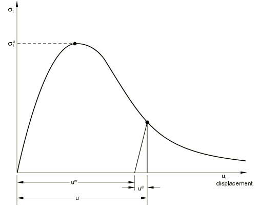
Typical values of range from 40 N/m (0.22 lb/in) for a typical construction concrete (with 20 MPa, 2850 lb/in2) to 120 N/m (0.67 lb/in) for a high strength concrete (with 40 MPa, 5700 lb/in2).
The implication of assuming that is a material property is that, when the elastic part of the displacement, is eliminated, the relationship between the stress and the remaining part of the displacement, is fixed, regardless of the specimen size. For example, consider a specimen developing a single crack across its section as tensile displacement is applied to it: is the displacement across the crack and is not changed by using a longer or shorter specimen in the test (so long as the specimen is significantly longer than the width of the crack band, which will typically be of the order of the aggregate size). Thus, one important part of the cracked concrete's tensile behavior is defined in terms of a stress/displacement relationship. In the finite element implementation of this model we must, therefore, compute the relative displacement at an integration point to provide . We do this in Abaqus by multiplying the strain by a characteristic length associated with the integration point. The characteristic crack length is based on the element geometry and formulation: it is a typical length of a line across an element for a first-order element; it is half of the same typical length for a second-order element. For beams and trusses it is a characteristic length along the element axis. For membranes and shells it is a characteristic length in the reference surface. For axisymmetric elements it is a characteristic length in the r–z plane only. For cohesive elements it is equal to the constitutive thickness. This definition of the characteristic length is used because we do not necessarily know in which direction the concrete will crack and so cannot choose the length measure in any particular direction. Thus, if there are elements in the model that have large aspect ratios, the model will likely provide different results if it is loaded in different directions and cracking occurs in such elements. This effect should be considered by the user in defining values for the material properties.
In reinforced concrete the – relationship must also represent the action of the bond between the concrete and the rebar as the concrete cracks. We assume this is accommodated by increasing the value of based on comparisons with experiments on reinforced material.
We first describe the crack detection plasticity model and then discuss the damaged elasticity.
![]()
Strain rate decomposition
We decompose the elastic strain rate of Equation 1 as
where is the total mechanical strain rate for the crack detection problem, is the elastic strain rate, and is the plastic strain rate associated with the crack detection surface.
![]()
Yield
The crack detection surface is the Coulomb line
where is the failure stress in uniaxial tension and is a constant that is defined from the value of the tensile failure stress, , in a state of biaxial stress when the other nonzero principal stress, , is at the uniaxial compression ultimate stress value, . is a hardening parameter ( is the equivalent uniaxial tensile stress). The hardening is measured by , with the relationship defined from the user-specified tension stiffening data (see Figure 5).
The stress measures and are defined in the same way as p and q, except that all stress components associated with open cracks (that is, if or is a crack direction in which the direct strain or ) are not included in these measures: they are invariants in subspaces of the stress space.
This surface has a simple mathematical form but matches plane stress data quite well. The hardening is introduced in the particular form shown in Equation 11 so that, as , the surface becomes , which in (p–q) space is the cone containing the principal axes of stress. This means that, as the tension stiffening is exhausted in a plane stress test, the stress point will drop back onto the nearest principal stress axis.
The value of is obtained as follows. The failure surface data include a definition of f, a ratio that states that, in a plane stress test cracking would occur when one principal stress has the value ( is the magnitude of the ultimate stress in uniaxial compression) and the other nonzero principal stress has the value . Another value provided as part of the failure surface data is , which defines
Cracking would, therefore, occur at the point with principal stresses , , and 0. For these values
and
Therefore, with ,
so
The crack detection surface is shown in Figure 2 and Figure 3.
![]()
Flow
The crack detection model uses the assumption of associated flow, so if and ,
otherwise, .
![]()
Hardening
The user defines the tension stiffening behavior by specifying the magnitude of the stress, , in a uniaxial tension test as a function of the inelastic strain. (When the fracture energy concept is used to define the postfailure behavior, “strain” is now defined as , where c is the characteristic length associated with the integration point.) The relationship is defined as follows.
Using the definition of , Equation 11, in the flow rule above we write
In uniaxial tension and . Therefore, in uniaxial tension,
and, hence,
Upon integration Equation 13 gives from ; and, therefore, the relationship is obtained from the tension stiffening input data.
![]()
Damaged elasticity
Following crack detection we use damaged elasticity to model the failed material. The elasticity is written in the form
where is the elastic stiffness matrix for the concrete.
Let represent a cracked direction, with corresponding direct stress and direct elastic strain . In these expressions and in the remainder of this section, no summation is implied by repeated indices with a bar over them. If the fracture energy concept is used, the strains are related to the user-specified stress/displacement definition for the tension stiffening behavior by , where c is the characteristic length associated with the integration point.
Then, in , is the usual elasticity of the concrete if . If ,
where is the stress corresponding to (as defined in the tension stiffening data), and
If ,
which follows from the tension stiffening data.
We also assume no Poisson effect for open cracks: for , for , .
The shear terms in the elasticity associated with existing crack directions are
where and In these expressions G is the elastic shear modulus, is a constant defined by the user as part of the shear retention data (see Figure 6),
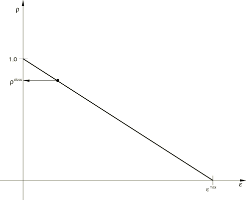
and is a linear function of , and is also defined by the user in the shear retention data. Here , where and are Macauley brackets, defining
for any function f.
![]()
Cracking
As soon as the crack detection surface () has been activated, we assume that cracking has occurred. The crack direction, , is taken to be the direction of that part of the maximum principal plastic strain increment conjugate to the crack detection surface, , that is orthogonal to the directions of any existing cracks at the same point. This crack orientation is stored for subsequent calculations, which are done for convenience in a local coordinate system oriented so that one of the coordinate directions is the crack direction, . Cracking is irrecoverable in the sense that, once a crack has occurred at a point, it remains throughout the rest of the calculation. Following crack detection, the crack affects the calculations by damaging the elasticity, as defined above. In addition, if the elastic strain across a crack is tensile, the invariants used in the crack detection surface are defined in the stress sub-space in which all stress components associated with the open crack direction are neglected, as described in the section above on yield. This implies that no more than three cracks can occur at any point (two in a plane stress case, one in a uniaxial stress case).
![]()
Integration of the model
The model is integrated using the backward Euler method generally used with the plasticity models in Abaqus. A material Jacobian consistent with this integration operator is used for the equilibrium iterations.