*SECTION FILE | |||||||
|
| ||||||
ProductsAbaqus/Standard
TypeHistory data
LevelStep
Required parameters
- NAME
-
Set this parameter equal to a label that will be used to identify the output for the section. Section names in the same input file must be unique.
- SURFACE
-
Set this parameter equal to the name used in the SURFACE option to define the surface.
![]()
Optional parameters
- AXES
-
Set AXES=LOCAL if output is desired in the local coordinate system. Set AXES=GLOBAL (default) to output quantities in the global coordinate system.
- FREQUENCY
-
Set this parameter equal to the output frequency, in increments. The output will always be printed at the last increment of each step unless FREQUENCY=0. The default is FREQUENCY=1. Set FREQUENCY=0 to suppress the output.
- UPDATE
-
Set UPDATE=NO if output is desired in the original local system of coordinates. Set UPDATE=YES (default) to output quantities in a local system of coordinates that rotates with the average rigid body motion of the surface section. This parameter is relevant only if AXES=LOCAL and the NLGEOM parameter is active in the step.
![]()
Optional data lines
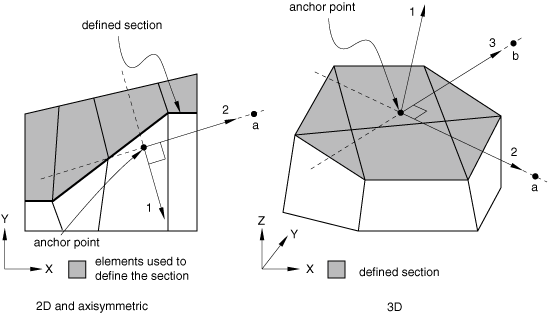
- First line
Node number of the anchor point (blank if coordinates given).
First coordinate of the anchor point (ignored if node number given).
Second coordinate of the anchor point (ignored if node number given).
Third coordinate of the anchor point (for three-dimensional cases only; ignored if node number given).
Leave this line blank to allow Abaqus to define the anchor point.
- Second line
Node number used to specify point a in Figure 1 (blank if coordinates given).
First coordinate of point a (ignored if node number given).
Second coordinate of point a (ignored if node number given).
- The remaining data items are relevant only for three-dimensional cases.
Third coordinate of point a (ignored if node number given).
Node number used to specify point b (blank if coordinates given).
First coordinate of point b (ignored if node number given).
Second coordinate of point b (ignored if node number given).
Third coordinate of point b (ignored if node number given).
Leave this line blank to allow Abaqus to define the axes.
- Third line
Give the identifying keys for the variables to be output. The keys are defined in the “Section variables” section of Abaqus/Standard output variable identifiers.
Omit both the first and second data lines for AXES=GLOBAL or to allow Abaqus to define the anchor point and the axes for AXES=LOCAL. Repeat the third data line as often as necessary to define the variables to be written to the results file. If this line is omitted, all appropriate variables (Output to the Data and Results Files) will be output.