ProductsAbaqus/StandardAbaqus/ExplicitAbaqus/CAE
TypeModel data
LevelPartPart instanceAssembly
Abaqus/CAEElement-based surfaces are supported by the Surface toolset. Node-based surfaces are not supported; if node-based surfaces are imported into Abaqus/CAE, they are treated as sets.
Required parameters
- NAME
-
Set this parameter equal to a label that will be used to refer to the surface.
![]()
Required parameter for cavity radiation simulations
- PROPERTY
-
This parameter applies only to Abaqus/Standard analyses.
Set this parameter equal to the name of the SURFACE PROPERTY definition associated with this surface. See Cavity Radiation in Abaqus/Standard.
![]()
Optional parameters
- COMBINE
-
Set COMBINE=UNION to create a surface based on the union of two or more surfaces of the same type.
Set COMBINE=INTERSECTION to create a surface based on the intersection of two surfaces of the same type.
Set COMBINE=DIFFERENCE to create a surface based on the difference of two surfaces of the same type (the second surface is subtracted from the first).
Only the NAME parameter and, in cavity radiation simulations, the PROPERTY parameter can be used in conjunction with this parameter.
- CROP
-
Include this parameter to create a new surface that will contain only those faces from an existing surface that have nodes in a specified rectangular box.
Only the NAME parameter and, in cavity radiation simulations, the PROPERTY parameter can be used in conjunction with this parameter.
- DEFINITION
-
This parameter is relevant only for surfaces defined using TYPE=CUTTING SURFACE.
Set DEFINITION=COORDINATES (default) to define the cutting plane by giving the coordinates of a point on the cutting plane and the normal to the cutting plane.
Set DEFINITION=NODES to define the cutting plane by giving global node numbers for point a on the cutting plane and point b that lies off the cutting plane with the cutting plane normal determined by the vector from a to b.
- FILLET RADIUS
-
This parameter can be used with TYPE=SEGMENTS, TYPE=CYLINDER, or TYPE= REVOLUTION to define a radius of curvature to smooth discontinuities between adjoining straight-line segments, adjoining circular-arc segments, and adjoining straight-line and circular-arc segments.
- INTERNAL
-
Abaqus/CAE uses the INTERNAL parameter to identify surfaces that are created internally. The INTERNAL parameter is used only in models defined in terms of an assembly of part instances. The default is to omit the INTERNAL parameter.
- REGION TYPE
-
This parameter is relevant only for surfaces defined on the boundary of an adaptive mesh domain. A surface defined in the interior of an adaptive mesh domain will move independently of the material unless the surface is constrained by mesh constraints. See Defining ALE adaptive mesh domains in Abaqus/Explicit.
Set REGION TYPE=LAGRANGIAN to create a Lagrangian boundary region. The edge of a Lagrangian boundary region will follow the material while allowing adaptive meshing along the edge and within the interior of the region.
Set REGION TYPE=SLIDING (default) to create a sliding boundary region. The edge of a sliding boundary region will slide over the material. Adaptive meshing will occur on the edge and within the interior of the region. Mesh constraints are typically applied on the edge of a sliding boundary region to fix it spatially.
Set REGION TYPE=EULERIAN to create an Eulerian boundary region in an adaptive mesh domain. This option is used to create a boundary region across which material can flow. Mesh constraints must be used normal to an Eulerian boundary region to allow material to flow through the region. If no mesh constraints are applied, an Eulerian boundary region will behave in the same way as a sliding boundary region.
- TRIM
-
Set TRIM=YES to invoke trimming of open free surfaces. Set TRIM=NO to suppress surface trimming. The default value is TRIM=YES unless the surface is used as a master surface in a finite-sliding contact formulation in Abaqus/Standard or the surface is used with the contact pair algorithm in Abaqus/Explicit. TRIM=YES has no effect on surfaces used with the contact pair algorithm in Abaqus/Explicit.
- TYPE
-
Set TYPE=ELEMENT (default) to define a free surface automatically for the elements specified or to define a surface on the elements by using element face identifiers.
Set TYPE=NODE to define a surface by specifying a list of nodes or node set labels.
Set TYPE=SEGMENTS to create a two-dimensional analytical surface in the plane for planar models or in the plane for axisymmetric models by defining connected line segments.
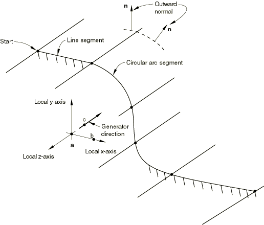
Set TYPE=CYLINDER to define a three-dimensional analytical surface by sweeping connected line segments defined in a local (x, y) plane along a specified generator vector.
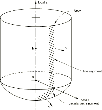
Set TYPE=REVOLUTION to define a three-dimensional analytical surface by providing connected line segments, which are given in an plane and are rotated about an axis.
Set TYPE=CUTTING SURFACE to generate an interior element-based surface using a cutting plane passing through an element set. The generated surface is an approximation to the cutting plane.
Set TYPE=EULERIAN MATERIAL to define a surface on the exterior boundary of an Eulerian material instance. This option applies only to Abaqus/Explicit.
Set TYPE=USER to define an analytical surface via user subroutine RSURFU in Abaqus/Standard.
Set TYPE=XFEM to generate a crack surface for enriched cracked elements. This option applies only to Abaqus/Standard. Crack surfaces for XFEM are not supported with the CONTACT PAIR option.
![]()
Additional optional parameters used for contact pair analyses in Abaqus/Explicit
- MAX RATIO
-
Set this parameter equal to the upper bound of the ratio of a facet's contact thickness to its minimum edge (or diagonal) length. This ratio is computed after the SCALE THICK parameter is applied to the contact thickness. The contact thickness for individual facets will be adjusted, if necessary, to conform to this maximum ratio.
If this parameter is omitted, no upper bound will be enforced. If this parameter is included without a value specified, the default value is 0.6.
- NO OFFSET
-
Include this parameter to indicate that this surface will ignore the midplane offset of any shell, membrane, or rigid elements that form the surface.
- NO THICK
-
Include this parameter to indicate that this surface will ignore the thickness of any shell, membrane, or rigid elements that form the surface. A surface defined with this parameter cannot be used to define a double-sided surface or for self-contact.
- SCALE THICK
-
This parameter applies only when the surface is used with the CONTACT PAIR option.
Set this parameter equal to the amount by which to scale the thicknesses of the underlying elements to compute the contact thicknesses. The default is 1.0 (i.e., no scaling).
![]()
Data lines for COMBINE=UNION
- First line
-
List of surfaces.
Repeat this data line as often as necessary. Up to 16 entries are allowed per line.
-
![]()
Data line for COMBINE=INTERSECTION or COMBINE=DIFFERENCE
- First (and only) line
-
First surface name.
-
Second surface name.
-
For COMBINE=DIFFERENCE the second surface is subtracted from the first.
![]()
Data lines to define a surface when the CROP parameter is included
- First line
-
Surface name.
-
- Second line
-
X-coordinate of the lower box corner.
-
Y-coordinate of the lower box corner.
-
Z-coordinate of the lower box corner.
-
X-coordinate of the opposite box corner.
-
Y-coordinate of the opposite box corner.
-
Z-coordinate of the opposite box corner.
-
- Third line (optional)
-
-
X-coordinate of the first point defining the orientation.
-
Y-coordinate of the first point defining the orientation.
-
Z-coordinate of the first point defining the orientation.
-
X-coordinate of the second point defining the orientation.
-
Y-coordinate of the second point defining the orientation.
-
Z-coordinate of the second point defining the orientation.
-
![]()
Data lines to define a surface using elements or element sets when the TYPE=ELEMENT parameter is used
- First line
-
Element set name or element number. In Abaqus/Explicit a blank data line can be specified to automatically generate the exterior (free) faces of every element in the model.
-
Face or edge identifier label (see Element-based surface definition for the face and edge identifiers for various elements) or the “word” EDGE (optional).
Repeat this data line as often as necessary to define the surface.
-
![]()
Data lines to define a surface using nodes or node sets when the TYPE=NODE parameter is used
- First line
-
Node set name or node number.
-
Cross-sectional area or distributing weight factor. In Abaqus/Standard contact calculations, the default is the area specified in the associated SURFACE INTERACTION option if the surface is defined in a contact pair; otherwise, a unit area is used. In Abaqus/Explicit the cross-sectional area used for contact pair calculations for node-based surface nodes is always set to 1.0 regardless of the value specified here. If the surface is used in a COUPLING or SHELL TO SOLID COUPLING definition, the default distributing weight factor is zero in Abaqus/Standard and 1.0 in Abaqus/Explicit.
Repeat this data line as often as necessary to define the surface.
-
![]()
Data lines to define a surface using a plane cutting through the given element sets when TYPE=CUTTING SURFACE, DEFINITION=COORDINATES
- First line
-
X-coordinate of a point on the cutting plane in the initial configuration.
-
Y-coordinate of a point on the cutting plane in the initial configuration.
-
Z-coordinate of a point on the cutting plane in the initial configuration.
-
X-component of a normal to the cutting plane in the initial configuration.
-
Y-component of a normal to the cutting plane in the initial configuration.
-
Z-component of a normal to the cutting plane in the initial configuration.
-
- Second line
-
List of elements or element set labels to be cut by the cutting plane to generate an element-based surface that is an approximation to the cutting plane. A blank data line can be specified to generate a surface by cutting the whole model.
Repeat this data line as often as necessary. Up to 16 entries are allowed per line.
-
![]()
Data lines to define a surface using a plane cutting through the given element sets when TYPE=CUTTING SURFACE, DEFINITION=NODES
- First line
-
Node number of the node at point a.
-
Node number of the node at point b.
-
- Second line
-
List of elements or element set labels to be cut by the cutting plane to generate an element-based surface that is an approximation to the cutting plane. A blank data line can be specified to generate a surface by cutting the whole model.
Repeat this data line as often as necessary. Up to 16 entries are allowed per line.
-
![]()
Data line to define surfaces created with TYPE=EULERIAN MATERIAL
- First line
-
Name of the material instance as defined in the EULERIAN SECTION.
Abaqus/Explicit will automatically create a surface on the exterior of the given material.
-
![]()
Data lines to define a crack surface created with TYPE=XFEM
- First line
-
List of names of the enriched features as defined with the ENRICHMENT option.
Abaqus/Standard will automatically generate a crack surface as the enriched elements crack.
Repeat this data line as often as necessary. Up to 16 entries are allowed per line.
-
![]()
No data lines are needed for TYPE=USER
![]()
Data lines to define surfaces created with TYPE=SEGMENTS
- First line
-
The “word” START.
-
Global X-coordinate or r-coordinate of the starting point of the line segments.
-
Global Y-coordinate or z-coordinate of the starting point of the line segments.
Second and subsequent data lines define the various line, circular, and parabolic segments (see below for their format) that form the profile of the analytical surface.
-
![]()
Data lines to define surfaces created with TYPE=CYLINDER
- First line (leave blank if this surface is being defined within a part or a part instance)
-
Global X-coordinate of point a, the origin of the local system (see Figure 1).
-
Global Y-coordinate of point a, the origin of the local system.
-
Global Z-coordinate of point a, the origin of the local system.
-
Global X-coordinate of point b on the local x-axis.
-
Global Y-coordinate of point b on the local x-axis.
-
Global Z-coordinate of point b on the local x-axis.
-
- Second line (leave blank if this surface is being defined within a part or a part instance)
-
Global X-coordinate of point c on the local cylinder generator vector.
-
Global Y-coordinate of point c on the local cylinder generator vector.
-
Global Z-coordinate of point c on the local cylinder generator vector.
-
- Third line
-
The “word” START.
-
Local x-coordinate of the starting point of the line segments.
-
Local y-coordinate of the starting point of the line segments.
Fourth and subsequent data lines define the various line, circular, and parabolic segments (see below for their format) that form the profile of the analytical surface.
-
![]()
Data lines to define surfaces created with TYPE=REVOLUTION
- First line (leave blank if this surface is being defined within a part or a part instance)
-
Global X-coordinate of point a, the origin of the local system (see Figure 2).
-
Global Y-coordinate of point a, the origin of the local system.
-
Global Z-coordinate of point a, the origin of the local system.
-
Global X-coordinate of point b on the symmetry axis (the local z-axis).
-
Global Y-coordinate of point b on the symmetry axis (the local z-axis).
-
Global Z-coordinate of point b on the symmetry axis (the local z-axis).
-
- Second line
-
The “word” START.
-
Local r-coordinate of the starting point of the line segments.
-
Local z-coordinate of the starting point of the line segments.
Third and subsequent data lines define the various line, circular, and parabolic segments (see below for their format) that form the profile of the analytical surface.
-
![]()
Data lines that define the line segments that form the analytical surface for TYPE=SEGMENTS, TYPE=CYLINDER, and TYPE=REVOLUTION
- Data line to define a straight line segment
-
The “word” LINE.
-
x-coordinate of the end point of the line.
-
y-coordinate of the end point of the line.
-
- Data line to define a circular arc segment (the arc must be less than 179.74°)
-
The “word” CIRCL.
-
x-coordinate of the end point of the circular arc.
-
y-coordinate of the end point of the circular arc.
-
x-coordinate of the center (origin) of the circular arc.
-
y-coordinate of the center (origin) of the circular arc.
-
- Data line to define a parabolic arc segment
-
The “word” PARAB.
-
Local x-coordinate of the middle point along the parabolic arc.
-
Local y-coordinate of the middle point along the parabolic arc.
-
Local x-coordinate of the end point of the parabolic arc.
-
Local y-coordinate of the end point of the parabolic arc.
For surfaces created with TYPE=SEGMENTS, the x- and y-coordinates are the global X- and Y-coordinates or r- and z-coordinates. For surfaces created with TYPE=CYLINDER, the x- and y-coordinates are the local x- and y-coordinates. For surfaces created with TYPE=REVOLUTION, the x- and y-coordinates are the local r- and z-coordinates.
-