*RIGID SURFACE | ||||||||||
|
| |||||||||
ProductsAbaqus/StandardAbaqus/CAE
TypeModel data
LevelPartPart instance
Abaqus/CAEPart module
Required parameters
- ELSET
-
Set this parameter equal to the name of the element set containing the IRS-type elements or the three-dimensional drag chain elements that may interact with the rigid surface being defined.
The ELSET and NAME parameters are mutually exclusive.
- NAME
-
Set this parameter equal to a label that will be used to refer to the rigid surface being created. This surface name is used to define contact interaction with another surface through the CONTACT PAIR option.
The ELSET and NAME parameters are mutually exclusive.
- REF NODE
-
Set this parameter equal to either the node number of the rigid body reference node or the name of a node set containing the rigid body reference node. If the name of a node set is chosen, the node set must contain exactly one node.
This parameter is relevant only when the NAME parameter is used.
- TYPE
-
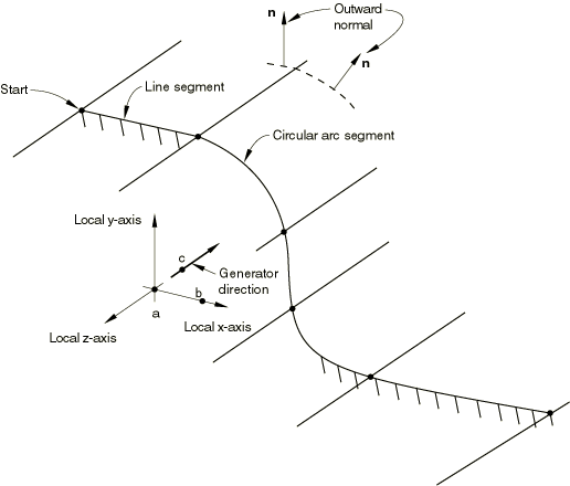
Set TYPE=SEGMENTS to create a two-dimensional rigid surface in the plane for planar models or in the plane for axisymmetric models by defining connected line segments.
Set TYPE=CYLINDER to define a three-dimensional rigid surface by providing connected line segments and then sweeping them along a specified generator vector.
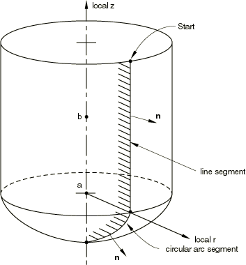
Set TYPE=REVOLUTION to define a three-dimensional rigid surface by providing connected line segments, which are given in an plane and are rotated about an axis.
Set TYPE=USER to define a rigid surface via user subroutine RSURFU.
![]()
Optional parameters
- FILLET RADIUS
-
This parameter can be used with TYPE=SEGMENTS, TYPE=CYLINDER, or TYPE=REVOLUTION to define a radius of curvature to smooth discontinuities between adjoining straight-line segments, adjoining circular-arc segments, and adjoining straight-line and circular-arc segments. It has no effect on rigid surfaces defined with TYPE=USER.
![]()
No data lines are needed for TYPE=USER
![]()
Data lines to define surfaces created with TYPE=SEGMENTS
- First line
The “word” START.
Global X-coordinate or r-coordinate of the starting point of the line segments.
Global Y-coordinate or z-coordinate of the starting point of the line segments.
![]()
Data lines to define surfaces created with TYPE=CYLINDER
- First line
Global X-coordinate of point a, the origin of the local system (see Figure 1).
Global Y-coordinate of point a, the origin of the local system.
Global Z-coordinate of point a, the origin of the local system.
Global X-coordinate of point b on the local x-axis.
Global Y-coordinate of point b on the local x-axis.
Global Z-coordinate of point b on the local x-axis.
- Second line
Global X-coordinate of point c on the local cylinder generator vector.
Global Y-coordinate of point c on the local cylinder generator vector.
Global Z-coordinate of point c on the local cylinder generator vector.
- Third line
The “word” START.
Local x-coordinate of the starting point of the line segments.
Local y-coordinate of the starting point of the line segments.
![]()
Data lines to define surfaces created with TYPE=REVOLUTION
- First line
Global X-coordinate of point a, the origin of the local system (see Figure 2).
Global Y-coordinate of point a, the origin of the local system.
Global Z-coordinate of point a, the origin of the local system.
Global X-coordinate of point b on the symmetry axis (the local z-axis).
Global Y-coordinate of point b on the symmetry axis (the local z-axis).
Global Z-coordinate of point b on the symmetry axis (the local z-axis).
- Second line
The “word” START.
Local r-coordinate of the starting point of the line segments.
Local z-coordinate of the starting point of the line segments.
![]()
Data lines that define the line segments that form the rigid surface for TYPE=SEGMENTS, TYPE=CYLINDER, and TYPE=REVOLUTION
- Data line to define a straight line segment
The “word” LINE.
x-coordinate of the endpoint of the line.
y-coordinate of the endpoint of the line.
- Data line to define a circular arc segment (the arc must be less than 180°)
The “word” CIRCL.
x-coordinate of the endpoint of the circular arc.
y-coordinate of the endpoint of the circular arc.
x-coordinate of the center (origin) of the circular arc.
y-coordinate of the center (origin) of the circular arc.
- Data line to define a parabolic arc segment
The “word” PARAB.
x-coordinate of the middle point along the parabolic arc.
y-coordinate of the middle point along the parabolic arc.
x-coordinate of the endpoint of the parabolic arc.
y-coordinate of the endpoint of the parabolic arc.
For rigid surfaces created with TYPE=SEGMENTS, the x- and y-coordinates are the global X- and Y-coordinates or r- and z-coordinates. For rigid surfaces created with TYPE=CYLINDER, the x- and y-coordinates are the local x- and y-coordinates. For rigid surfaces created with TYPE=REVOLUTION, the x- and y-coordinates are the local r- and z-coordinates.