Choosing a gasket element | ||||||||||
|
| |||||||||
ProductsAbaqus/StandardAbaqus/CAE
Naming convention
The gasket elements used in
Abaqus/Standard
are named as follows:

For example, GKPE4 is a 4-node, plane strain gasket element that accounts for
thickness-direction, membrane, and transverse shear behaviors.
![]()
Elements for general use versus elements with thickness-direction behavior only
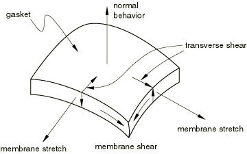
Abaqus/Standard offers two classes of gasket elements. In both classes material properties can be specified by either special gasket behavior models or built-in material models, including user-defined materials (see Defining the gasket behavior directly using a gasket behavior model and Defining the gasket behavior using a material model). The first class is a collection of gasket elements that have all displacement degrees of freedom active at their nodes. These elements are necessary when the membrane and/or transverse shear behavior of the gasket is of importance (see Figure 1). The thickness-direction, transverse shear, and membrane behaviors can be defined as uncoupled behaviors only, when the elements are used in conjunction with special gasket behavior models. In some cases the membrane effects are only secondary; in such cases it is possible to model only the thickness-direction and transverse shear behaviors. These elements are suited for analyses where both thickness-direction behavior and frictional effects are important.

In the second class of gasket elements deformation is measured only in the thickness direction. The response of the gasket to any other deformation mode is ignored. The nodes of these elements have only one displacement degree of freedom, which lies in the thickness direction of the gasket. This class of elements is intended as a means to reduce the computational cost of an analysis when the thickness-direction behavior of the gasket is the only behavior of importance. This behavior can be specified easily in terms of pressure in the gasket versus gasket closure. Frictional forces cannot be transmitted by such elements, and any thermal expansion or stretching of the gasket in its plane is not accounted for.
![]()
Elements for two-dimensional, three-dimensional, and axisymmetric analyses
For both classes of gasket elements Abaqus/Standard offers a choice of two-dimensional, three-dimensional, and axisymmetric elements. Plane stress and plane strain elements are provided for two-dimensional analyses to represent thin gaskets or thick gaskets in the out-of-plane direction, respectively. Axisymmetric gasket elements are provided for cases where the geometry and loading of the structure are axisymmetric.
Abaqus/Standard offers 2-node or link elements for two-dimensional, three-dimensional, and axisymmetric analyses; three-dimensional line elements; and a three-dimensional 12-node element for use with modified tetrahedral elements. These elements have specific characteristics that are useful when modeling gaskets.
Link elements
Because link gasket elements have two nodes, their geometry defines only one dimension of the gasket—the through-thickness dimension. A link gasket element might typically be used to model a washer used under a bolt, when the bolt itself is modeled with a truss element. For two-dimensional and three-dimensional link elements the cross-section of the gasket is undetermined. For axisymmetric link elements the width of the element is undetermined. The reduction in dimensionality of these elements offers flexibility in the specification of the gasket behavior and can prove to be very efficient in some cases; see Defining the gasket behavior directly using a gasket behavior model for further details.
Three-dimensional line elements
Three-dimensional line gasket elements are typically used to model narrow, thicker features in gaskets, such as an elastomeric insert around a hole. Since they are used in three-dimensional analyses, their width is undetermined from the element's geometry. This reduction in dimensionality offers flexibility in the specification of the gasket behavior and can prove to be very efficient in some cases; see Defining the gasket behavior directly using a gasket behavior model for further details.
12-node elements for use with modified tetrahedral elements
The 12-node gasket elements have the same contact properties as the modified 10-node tetrahedra; these elements have consistent nodal forces at the corner and midside nodes. They are primarily intended for use with the modified tetrahedral elements but can also be used in conjunction with other solid continuum elements by using contact pairs. In the latter case the solution may be noisy for badly mismatched meshes.