About gasket elements | ||
| ||
Abaqus/Standard offers a library of gasket elements to model the behavior of gaskets.
Motivation for gasket elements
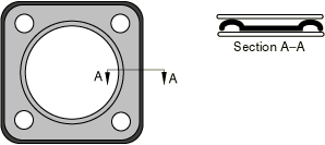
Gaskets are constructed in many ways and from many materials. Some types of gaskets consist of several layers of preformed metal, possibly with thin elastomeric coatings or elastomeric inserts (see Figure 1). Others use plastics together with elastomeric inserts.
Gaskets are usually very thin and act as sealing components between structural components. They are carefully designed to provide appropriate pressure-closure behaviors through their thickness (the thin direction of the gaskets) so that they maintain their sealing action as the components undergo deformations due to thermal and mechanical loads. It is difficult to use solid continuum elements to model the through-thickness behavior of gaskets with the material library available. Therefore, Abaqus/Standard offers a variety of gasket elements that have through-thickness behaviors specifically designed for the study of gaskets.
The gasket behavior models are separate from the models in the material library and assume that the thickness-direction, transverse shear, and membrane behaviors are uncoupled (see Defining the gasket behavior directly using a gasket behavior model for details). For a gasket behavior that is not readily addressed by these special behavior models, such as occurs when coupled behaviors or through-thickness tensile behavior must be considered, Abaqus/Standard provides a versatile alternative by allowing a gasket element to use either a built-in or user-defined material model (see Defining the gasket behavior using a material model for details).
![]()
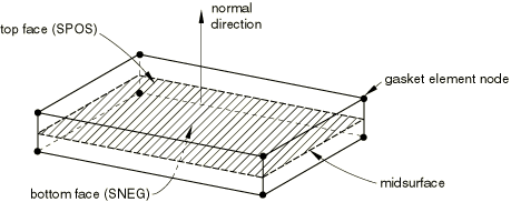
Spatial representation of a gasket element
Figure 2 demonstrates the key geometrical features that are used to define gasket elements. Gasket elements are composed of two surfaces separated by a thickness. The relative motion of the bottom and top surfaces measured along the thickness direction to the gasket quantifies the thickness-direction (local 1-direction) behavior of the gasket element. The relative change in position of the bottom and top surfaces measured in the plane orthogonal to the thickness direction quantifies the transverse shear behavior of the gasket element. The stretching and shearing of the midsurface of the element (the surface halfway between the bottom and top surfaces) quantifies the membrane behavior of the gasket element.
![]()
Local behavior directions defined at the integration points
The thickness direction defined at the integration points of gasket elements constitutes the local 1-direction. The transverse shear behavior is defined in the local 1–2 and 1–3 planes. The membrane behavior is defined in the 2–3 plane. The local 2- and 3-directions are not defined for elements that have nodes with only one degree of freedom because these elements consider only the thickness-direction behavior of a gasket. The local directions are used to specify the gasket behavior and for output of all quantities that describe the current deformation state of a gasket. Abaqus/Standard computes the local directions by default. You can also define them for some element types.
Default local directions
Abaqus/Standard computes the local 1-direction as explained in Defining the gasket element's initial geometry.
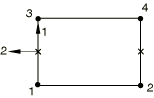
For two-dimensional and axisymmetric gasket elements, the local 2-direction is defined so that the cross product between the local 1- and 2-directions gives the out-of-plane direction (see Figure 3).
For three-dimensional area and three-dimensional link elements, the local 2- and 3-directions are normal to the local 1-direction (see Figure 4) and are defined by the standard Abaqus convention for local directions on surfaces in space (see Conventions).
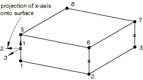
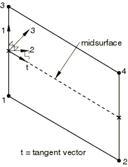
For three-dimensional line elements, the local 2-direction is obtained by the projection of the tangent to the midsurface of the element onto the plane orthogonal to the local 1-direction (see Figure 5). The local 3-direction is then obtained by the cross product of the local 1- and 2-directions.
Specifying the local directions
You can define the local 1-direction as explained in Defining the gasket element's initial geometry. The local 2- and 3-directions can be defined using local orientations (Orientations) for three-dimensional area and three-dimensional link elements that consider transverse shear and membrane deformations.
Input File Usage
Use the following option to associate a local orientation with a particular gasket element set:
GASKET SECTION, ELSET=name, ORIENTATION=name
Abaqus/CAE Usage
Property module: ![]()
Procedures with which gasket elements are allowed
Gasket elements can be used in static, static perturbation, quasi-static, dynamic, and frequency analyses. However, gasket elements are assumed to have no mass; therefore, the density cannot be defined for gasket elements.