Creating generalized plane strain sections | ||||||||
|
| |||||||
Context:
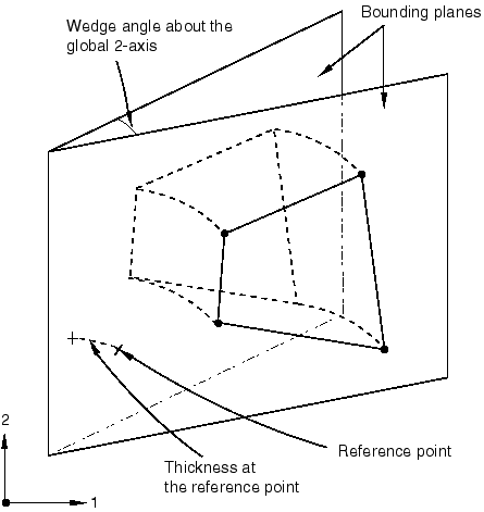
You must create a reference point to indicate the reference node required by generalized plane strain elements. In addition to the material and the section thickness at the reference point, you can specify wedge angles about the global 1- and 2-axes, as defined in Figure 1. For more information, see Generalized plane strain elements.
Figure 1. Generalized plane strain section definition.
From the main menu bar, select .
A Create Section dialog box appears.
Tip: You can also click in the Section Manager or select the create section tool  in the
Property module
toolbox.
in the
Property module
toolbox.
Select a material for the section. If desired, click
 to create a material; see
Creating or editing a material,
for more information.
to create a material; see
Creating or editing a material,
for more information.