Controlling beam profile display for postprocessing | |||||
|
| ||||
Context:
The rendering of beam profiles requires the presence of beam orientation data in the output database. Beam normals are written to the output database automatically for all the steps that include field output. For analyses that include geometric nonlinearity, you can display beam profiles during postprocessing only if nodal output is requested in the model. For more information, see Using a beam section integrated during the analysis to define the section behavior.
Abaqus/CAE does not render the tapering of beam profiles along their length. If your model includes tapered beam sections, Abaqus/CAE renders these beams using the beam's starting profile along its entire length. For more information about tapered beams, see Creating beam sections.
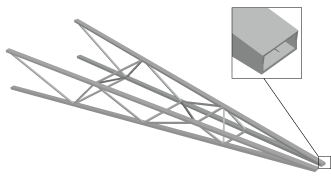
Displaying beam profiles is useful for checking that the correct profile has been assigned to a particular region and that the assigned beam orientation results in the expected orientation of the profile. For example, Figure 1 shows the box beam profiles displayed on the light-service crane described in Example: cargo crane.
Note:
If your results include quadratic beam elements, Abaqus/CAE does not consider the midside nodes in those elements when the beam profiles are rendered.
If you assign a general beam section to a wire, Abaqus/CAE displays the beam profile as an ellipse with a cross-sectional area and moments of inertia ( and ) that match the values you specified. If you assign a truss section to a wire, Abaqus/CAE displays the truss profile as a circle with a cross-sectional area that matches the value you specified.
Abaqus/CAE renders beam profiles according to the current settings for color coding and translucency. When these settings change, the color and translucency of the beam profiles change as well. When beam profiles are displayed, Abaqus/CAE disables scaling and shrinking of the model.