Controlling beam profile display | ||||||
|
| |||||
Context:
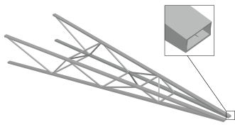
When beam profiles are displayed, Abaqus/CAE disables both view cuts and scaling and shrinking of the model. Displaying beam profiles is useful for checking that the correct profile has been assigned to a particular region and that the assigned beam orientation results in the expected orientation of the profile. For example, Figure 1 shows the box beam profiles displayed on the light-service crane described in Will link to gsa-bms-exacargocrane.
If you assign a general beam section to a wire, Abaqus/CAE displays the beam profile as an ellipse with a cross-sectional area and moments of inertia ( and ) that match the values you specified. If you assign a truss section to a wire, Abaqus/CAE displays the truss profile as a circle with a cross-sectional area that matches the value you specified.
Abaqus/CAE does not render the tapering of beam profiles along their length. If your model includes tapered beam sections, Abaqus/CAE renders these beams using the beam's starting profile along its entire length. For more information about tapered beams, see Creating beam sections.
Abaqus/CAE renders beam profiles according to the current settings for color coding and translucency. When these settings change, the color and translucency of the beam profiles change as well.