Bottom-up meshing methods | ||
| ||
- Sweep
The sweep method creates a three-dimensional mesh by moving a two-dimensional mesh along a sweep path. The sweep method is illustrated in Figure 2. You should use the bottom-up sweep meshing method when the region cross-section changes between the starting and ending sides. To use the sweep method, you must first choose a Source side that defines the face or faces on which Abaqus/CAE will create a two-dimensional mesh. The source side can be any combination of geometric faces, element faces, and two-dimensional elements. You can define the sweep path by selecting Connecting sides that define the sides of the desired sweep region. If you define connecting sides, the mesh conforms closely to the geometry or mesh along the selected sides. Alternatively, for geometry you can select a Target side and specify a Number of layers and allow Abaqus/CAE to create the sweep path by interpolating between the source and target sides. The Target side is a single face that Abaqus/CAE uses to end the mesh. The number of layers refers to the number of element layers that will be placed between the source and the target sides—if you use connecting sides, the two-dimensional meshes of the connecting sides define the number of element layers. Abaqus/CAE sweeps the two-dimensional mesh from the source side into the volume of the solid region to create the mesh.
- Extrude
The extrude method is a special case of the sweep method with a linear path defined by a direction and a distance. The extrude method is illustrated in Figure 3. You should use the extrude method for regions with a constant cross-section and a linear sweep path. There are three required parameters for a bottom-up extruded mesh. As with the sweep method, you choose the Source side that defines the area on which Abaqus/CAE will create a two-dimensional mesh. You then select the starting and ending point of a Vector that defines the extrusion direction and can also be used to define the extrusion distance. Finally, you indicate the Number of layers to define the number of elements between the source side and the end of the extruded mesh. If you use the vector to define the extrusion distance, the definition is complete. However, you can Specify a distance or use Project to target and select a target side to define the extrusion distance. The target side can be selected from any geometry, mesh, or datum plane in the viewport; it need not be part of the same part instance as the source. Abaqus/CAE extrudes the two-dimensional mesh from the source side in the direction of the extrusion vector. If you select a target side to define the extrusion distance, Abaqus/CAE ends the extruded mesh at the target side. Figure 1 shows the source side and target side on the left; the extrusion vector (not shown) extends from the center of the rectangular source side to the center of the cylinder. The resulting extruded mesh is an extension of the source side mesh. It closely matches the target side shape, but no attempt is made to match the node positions of the mesh on the target side.
Figure 1. The optional target side (colored white) is used to define the extrusion distance.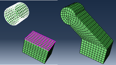
The Bias ratio parameter defines a change in the element thickness between the source side and the end of an extruded bottom-up mesh in which more than one layer is created. The bias ratio is the ratio of the thickness of the first layer of elements in the extruded mesh to the thickness of the last layer of elements. The default bias ratio of 1.0 has equal thickness elements throughout the extrusion distance.
- Revolve
The revolve method is another special case of the sweep method. In this case the sweep path is a circular path defined by an axis and an angle of revolution. The revolve method is illustrated in Figure 2. You should use this method for regions with a constant cross-section and a circular sweep path. As with the sweep and extrude methods, you choose the Source side that defines the area on which Abaqus/CAE will create a two-dimensional mesh. The source side cannot intersect the axis of revolution, but it may contain edges that coincide with the axis. If so, the elements contacting the axis create a layer of wedge elements in the revolved mesh. The source side should not include any triangular elements along the axis of revolution. You then select the starting and ending point of an Axis that defines the axis of revolution. Finally, you indicate the Angle and the Number of layers to define the number of elements between the source side and the end of the revolved mesh. Abaqus/CAE revolves the two-dimensional mesh from the source side by the specified angle and evenly divides the resulting region into the desired number of element layers. The direction of revolution is clockwise if you look along the axis of revolution from the starting point to the ending point.
Figure 2. The bottom-up revolve method sweeps the source side mesh by the specified angle about the axis.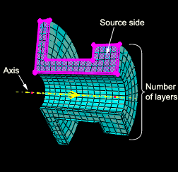
- Offset
The offset method works the same as Offset (create solid layers) in the Edit Mesh toolset; it creates one or more layers of solid elements by offsetting the selected elements. Offset is available only when you are working with orphan elements. To create an offset bottom-up mesh, you enter a total thickness for the offset elements and the desired number of element layers. You can create an element set or extend an existing set, but you cannot create top and bottom surfaces as you can with the Edit Mesh toolset. If you select shell elements as the source, you must indicate in the prompt area the desired offset direction; you can offset shell elements in both directions. If your shell element selection contains sharp corners, toggle on Constant thickness around corners to maintain the same total thickness where the elements meet in the corner as in the rest of the selection. Using this option can reduce element distortion and prevent collapsed elements, especially if elements are offset to the inner side of a corner (for more information, see Reducing element distortion and collapse during mesh offsetting).