Reducing element distortion and collapse during mesh offsetting | ||
| ||
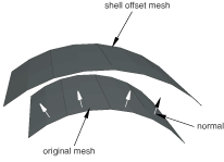
offsetting the nodes normal to the boundary of an existing mesh surface, and
building elements that propagate out in the normal direction.
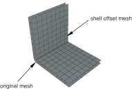
When you create a mesh that is offset from a concave mesh surface, the elements tend to converge, as shown in Figure 1.

As a result, elements may collapse or become inverted, and the magnitude of the offset is limited by a combination of the degree of curvature and the element size, as shown in Figure 2.
You can try to avoid element collapse and element inversion by selecting Constant thickness around corners from the Offset Mesh dialog box. When this option is selected, Abaqus/CAE tapers the offset elements that propagate from sharp corners. The resulting elements have a constant nodal offset distance as opposed to a constant distance between the layers of the element faces. Figure 3 illustrates the effect on the offset mesh pattern of requesting a constant thickness around corners.
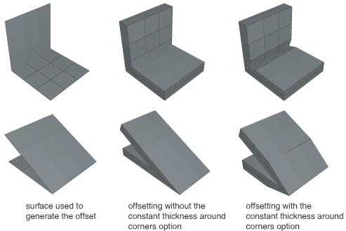
The effect on the offset mesh pattern is similar for both solid and shell offset meshes. You can also reduce element distortion by using a larger element size in the location of the concave region. However, you can control the element size only if you can regenerate the mesh from which you are offsetting.
In contrast, when you create a mesh that is offset from a convex mesh surface, the elements tend to fan out, as shown in Figure 4.