What is bottom-up meshing? | ||
| ||
You can apply bottom-up meshing to any solid region, including regions that can be meshed using the top-down techniques, and to meshes that do not have any associated geometry. Since bottom-up meshing is a manual process that can be very time consuming, it is recommended that you use this method only when the top-down methods fail to produce a satisfactory mesh.
Generating the desired mesh may require multiple applications of the bottom-up meshing technique. If multiple applications are required, each bottom-up mesh becomes an incremental building block for the next mesh until you complete the mesh for the region. Each application of the bottom-up meshing technique involves four phases:
You select the domain within which Abaqus/CAE will create the mesh. You can choose either a three-dimensional geometry region or orphan elements.
You select the method that Abaqus/CAE will use to create the mesh. You can choose from the following methods:
Sweep
Extrude
Revolve
Offset (available only for orphan element selections)
You select the side, called the source side, that Abaqus/CAE will use to create a two-dimensional mesh to be swept, extruded, or revolved to fill a three-dimensional region.
You select the remaining parameters to complete the definition of the bottom-up mesh. For example, if you chose the sweep method, you can choose connecting sides and a target side.
In addition, you may need to edit bottom-up meshes or associate them with geometry before you can use them to continue generating the region mesh. For more information, see The Edit Mesh toolset.”
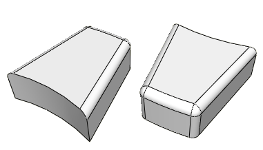
Figure 1 shows a part that cannot be meshed with hexahedral elements using top-down techniques.
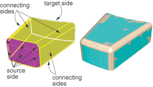
The bottom-up sweep method was used to mesh the part in Figure 2. The user selected six faces for the source side (magenta), selected the hidden rear face as the target side (white), and used the six remaining sides as connecting sides (yellow), as indicated in the figure. In this example the selected sides are all geometric faces; Abaqus/CAE also allows you to select element faces and two-dimensional elements to define the source side and the connecting sides of a bottom-up mesh.
You can choose from the sweep, extrude, or revolve methods to mesh a selected geometric region, and you can also choose the offset method if you are working with orphan elements. Depending on the shape of the region and the analysis intent, more than one method may produce acceptable results. The method that you select and the corresponding parameters will determine how well the mesh conforms to the geometry, if applicable. For example, Figure 3 shows the same part as Figure 2; this time the part is meshed with the extrude method. The parameters for the extrude method are a source side, an extrusion vector, and a number of layers. As shown in Figure 3, the extruded mesh does not capture the tapered sides and the rounded corners at the back of the model.
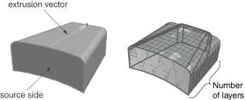
If these details are not important, this simplified mesh may be acceptable. Alternatively, you could edit the resulting mesh by modifying or removing the nodes and elements that extend beyond the original geometry. For more information on editing a mesh, see The Edit Mesh toolset.”
If a resulting bottom-up mesh is not acceptable, you can delete it and try a different bottom-up method for the same region or partition the region and mesh the resulting simpler regions. You can also use the mesh Undo and Redo functions to undo steps in the bottom-up meshing procedure rather than deleting the entire bottom-up mesh for the region and starting over.
Note:
Undo and redo are not available after some operations, such as deleting a region mesh.
The undo and redo functions are the same as those used for the Edit Mesh toolset (for more information, see Undoing or redoing a change in the Edit Mesh toolset).