Transient internal pressure loading of a viscoelastic cylinder | ||
| ||
ProductsAbaqus/Standard
Elements tested
CAX4I
CAX8R
CPE4I
CPE8R
![]()
Features tested
The automatic incrementation capability provided for integration of time-dependent material models and the use of the viscoelastic material model for a larger number of Prony series terms are tested in this problem. It also demonstrates the use of viscoelastic material models in dynamic analysis.
![]()
Problem description
The structure is a solid rocket motor, modeled as a long, hollow viscoelastic cylinder encased in a thin steel shell. The rocket's ignition is simulated by a transient internal pressure load acting at the inner diameter of the viscoelastic cylinder. The transient response of the structure is sought.
Model:
The viscoelastic cylinder has an inner radius of 10 mm and an outer radius of 50 mm. The steel case is 0.5 mm thick. We assume plane strain, with no gradient of the solution, in the axial direction. The problem is, therefore, modeled with a single row of axisymmetric, second-order, reduced-integration elements (CAX8R). The viscoelastic material is represented using 20 elements, while the case is modeled with a single element.
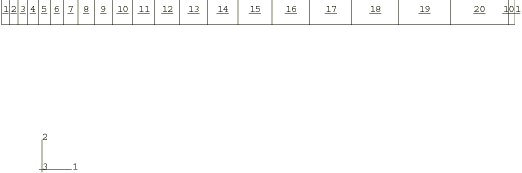
Mesh:
The mesh is shown in Figure 1. The mesh is finer toward the inner diameter of the cylinder, where the stresses are highest.
Material:
The extensional relaxation function of the viscoelastic material is defined using a six-term Prony series:
The instantaneous modulus, , is 1651.59 MPa; and the six pairs of relative moduli and time constants are
| i | sec | |
|---|---|---|
| 1 | 0.1986 | 0.281 × 10⁻⁷ |
| 2 | 0.1828 | 0.281 × 10⁻⁵ |
| 3 | 0.1388 | 0.281 × 10⁻³ |
| 4 | 0.2499 | 0.281 × 10⁻¹ |
| 5 | 0.1703 | 0.281 × 101 |
| 6 | 0.0593 | 0.281 × 10³ |
This model results in a very low long-term elastic modulus (0.4955 MPa), so the material almost behaves as a viscoelastic fluid. Because the viscoelastic material is incompressible throughout the problem, the relative moduli and time constants that constitute the extensional relaxation function can be used directly in the definition of the shear relaxation function. Contrast this with Viscoelastic rod subjected to constant axial load, in which the material is slightly compressible, so that the shear modulus and time constant were related to the extensional values through the bulk modulus.
A solution to the present problem is also obtained by modeling the behavior of the viscoelastic cylinder with large-strain linear viscoelastic theory. The relaxation behavior is defined in the same way, but the short-term elastic properties are specified as part of the hyperelastic material definition. The polynomial formulation with 1 is used, and the constants are = 275.247 MPa , = 0 (neo-Hookean material) and = 7. × 10−7 MPa−1. These constants are such that the initial Young's modulus and initial Poisson's ratio are equal to and , respectively. The steel case is assumed to be linear elastic, with a Young's modulus of 200 GPa and a Poisson's ratio of 0.3.
Loading:
The time-dependent pressure loading used in the static analyses is
A plot of this loading as a function of time is shown in Figure 2. To highlight inertia effects, the pressure loading in the dynamic analysis is applied 10 times faster:
These pressure histories are specified using user subroutine DLOAD.
![]()
Analysis
The static analysis is done using the quasi-static procedure with a time period of 0.5 sec. A tolerance on the accuracy of the transient creep solution is specified to enable automatic time incrementation. The accuracy tolerance is set to 7.0 × 10⁻³, which is the same order of magnitude as the maximum elastic strain.
The dynamic analysis is done using the dynamic procedure with a time period of 0.05 sec. This analysis is done based on nonlinear geometric behavior. A tolerance on the accuracy of the half-increment residual is specified to enable automatic incrementation. The value chosen (1000 N) is one order of magnitude higher than the highest equivalent nodal loads.
![]()
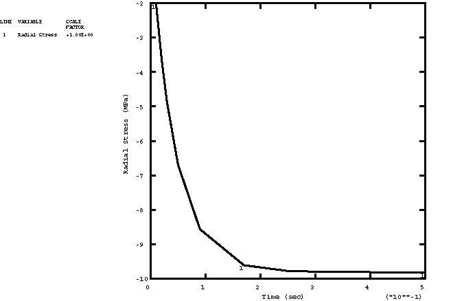
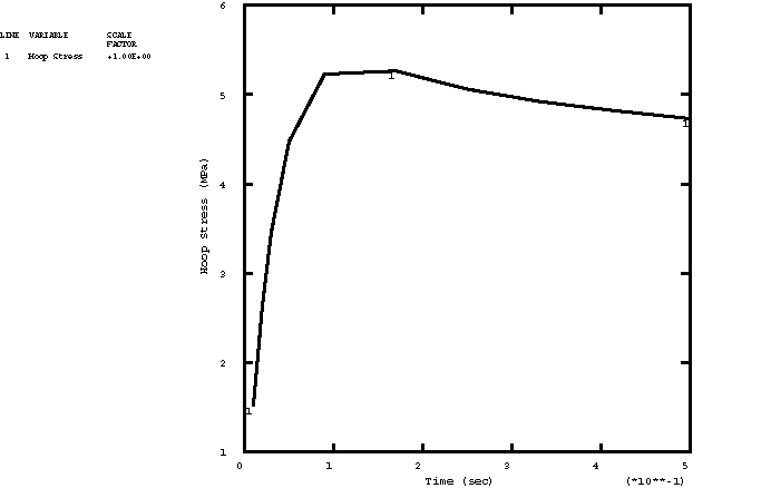
Results and discussion
Figure 3 through Figure 5 depict, respectively, the time histories of the radial stress, hoop stress, and hoop strain in the innermost element for a linear static analysis. The static analysis with the large-strain formulation gives almost identical results.
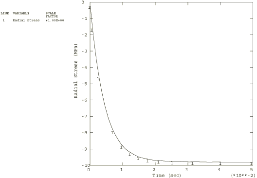
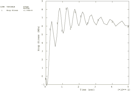
Figure 6 through Figure 8 depict, respectively, the time histories of the radial stress, hoop stress, and hoop strain in the innermost element for the nonlinear dynamic analysis.
![]()
Input files
- viscocylinder_cax8r_linear.inp
Linear static analysis.
- viscocylinder_cax8r_linear.f
User subroutine DLOAD used in viscocylinder_cax8r_linear.inp.
- viscocylinder_cax8r_static.inp
Nonlinear static analysis.
- viscocylinder_cax8r_static.f
User subroutine DLOAD used in viscocylinder_cax8r_static.inp.
- viscocylinder_cax8r_dyn.inp
Nonlinear dynamic analysis.
- viscocylinder_cax8r_dyn.f
User subroutine DLOAD used in viscocylinder_cax8r_dyn.inp.
- viscocylinder_cpe8r.inp
Uses a wedge of plane strain elements (CPE8R) to solve the linear static analysis.
- viscocylinder_cpe8r.f
User subroutine DLOAD used in viscocylinder_cpe8r.inp.
- viscocylinder_cax4i_linear.inp
Linear static analysis using CAX4I.
- viscocylinder_cax4i_linear.f
User subroutine DLOAD used in viscocylinder_cax4i_linear.inp.
- viscocylinder_cax4i_static.inp
Nonlinear static analysis using CAX4I.
- viscocylinder_cax4i_static_po.inp
POST OUTPUT analysis.
- viscocylinder_cax4i_static.f
User subroutine DLOAD used in viscocylinder_cax4i_static.inp.
- viscocylinder_cax4i_dyn.inp
Nonlinear dynamic analysis using CAX4I.
- viscocylinder_cax4i_dyn.f
User subroutine DLOAD used in viscocylinder_cax4i_dyn.inp.
- viscocylinder_cpe4i.inp
Linear static analysis using CPE4I.
- viscocylinder_cpe4i.f
User subroutine DLOAD used in viscocylinder_cpe4i.inp.
![]()
Figures