Pure bending of a cylinder: CAXA elements | ||
| ||
ProductsAbaqus/Standard
Elements tested
CAXA4n
CAXA4Rn
CAXA8n
CAXA8Rn
(n=1, 2, 3, 4)
![]()
Problem description
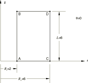
A hollow cylinder of circular cross-section, inner radius , outer radius , and length is subjected to a bending moment, M, applied to its end planes. For a linear elastic material with Young's modulus E and Poisson's ratio , the solutions for stress and displacement are as follows:
where is the moment of inertia of the cylinder and r, , and z are the cylindrical coordinates.
Only one-half of the structure is considered, with a symmetry plane at 0. The form of the displacement solution, which is a quadratic function in both r and z, suggests that a single second-order element should model the structure accurately. The full- and reduced-integration second-order elements do use a single element mesh, but an 8 × 12 mesh is used for the fully integrated first-order elements and a 16 × 24 mesh is used for the reduced-integration first-order elements.
Material:
Linear elastic, Young's modulus = 30 × 106, Poisson's ratio = 0.33.
Boundary conditions:
0 on the 0 plane; at on the 0 plane, at 0° is set equal to at 180° with an equation constraint to remove the rigid body motion in the global x-direction.
Loading:
The bending load is simulated by applying a surface traction of the form on the plane of the cylinder. This is done by applying the appropriate nonuniform pressure load with a distributed load and defining the variation of the pressure in both the r- and -directions with user subroutine DLOAD. In the user subroutine the value at each integration point, which is stored in COORDS(3), is expressed in degrees.
![]()
Results and discussion
The analytical solution and the Abaqus results for the CAXA8n, CAXA8Rn, CAXA4n, and CAXA4Rn (n=1, 2, 3, or 4) elements are tabulated below for a structure with and dimensions 6, 2, and 6. The output locations are at points , , , and on the 0° plane, as shown in the figure on the previous page, and at points , and H, which are at the corresponding locations on the 180° plane. The CAXA8n elements match the exact solution precisely.
| Variable | Exact | CAXA8n | CAXA8Rn | CAXA4n | CAXA4Rn |
|---|---|---|---|---|---|
| at A | 2 | 2 | 2.040 | 2.102 | 2.124 |
| at A | 0 | 0 | 0 | 0 | 0 |
| at A | 0 | 0 | 0 | 0 | 0 |
| at B | 2 | 2 | 2 | 2.098 | 2.091 |
| at B | −6 × 10⁻⁷ | −6 × 10⁻⁷ | −5.927 × 10⁻⁷ | −6.000 × 10⁻⁷ | −6.015 × 10⁻⁷ |
| at B | 4 × 10⁻⁷ | 4 × 10⁻⁷ | 4.164 × 10⁻⁷ | 3.996 × 10⁻⁷ | 3.984 × 10⁻⁷ |
| at C | 6 | 6 | 5.979 | 5.895 | 5.877 |
| at C | −1.76 × 10⁻⁷ | −1.76 × 10⁻⁷ | −1.881 × 10⁻⁷ | −1.757 × 10⁻⁷ | −1.762 × 10⁻⁷ |
| at C | 0 | 0 | 0 | 0 | 0 |
| at D | 6 | 6 | 6 | 5.898 | 5.908 |
| at D | −7.76 × 10⁻⁷ | −7.76 × 10⁻⁷ | −7.954 × 10⁻⁷ | −7.757 × 10⁻⁷ | −7.779 × 10⁻⁷ |
| at D | 1.2 × 10⁻⁶ | 1.2 × 10⁻⁶ | 1.211 × 10⁻⁶ | 1.200 × 10⁻⁶ | 1.203 × 10⁻⁶ |
| at E | −2 | −2 | −2.040 | −2.102 | −2.124 |
| at E | 0 | 0 | 0 | 0 | 0 |
| at E | 0 | 0 | 0 | 0 | 0 |
| at F | −2 | −2 | −2 | −2.098 | −2.091 |
| at F | 6 × 10⁻⁷ | 6 × 10⁻⁷ | 5.927 × 10⁻⁷ | 6.000 × 10⁻⁷ | 6.015 × 10⁻⁷ |
| at F | −4 × 10⁻⁷ | −4 × 10⁻⁷ | −4.164 × 10⁻⁷ | −3.996 × 10⁻⁷ | −3.984 × 10⁻⁷ |
| at G | −6 | −6 | −5.979 | −5.895 | −5.877 |
| at G | 1.76 × 10⁻⁷ | 1.76 × 10⁻⁷ | 1.881 × 10⁻⁷ | 1.757 × 10⁻⁷ | 1.762 × 10⁻⁷ |
| at G | 0 | 0 | 0 | 0 | 0 |
| at H | −6 | −6 | −6 | −5.898 | −5.908 |
| at H | 7.76 × 10⁻⁷ | 7.76 × 10⁻⁷ | 7.954 × 10⁻⁷ | 7.757 × 10⁻⁷ | 7.779 × 10⁻⁷ |
| at H | −1.2 × 10⁻⁶ | −1.2 × 10⁻⁶ | −1.211 × 10⁻⁶ | −1.200 × 10⁻⁶ | −1.203 × 10⁻⁶ |
Note:
The results are independent of n, the number of Fourier modes.
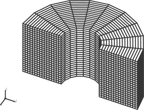
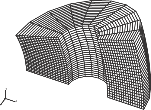
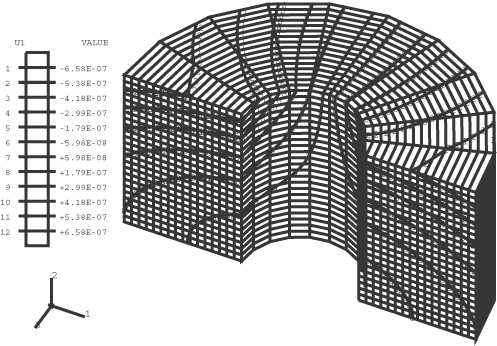
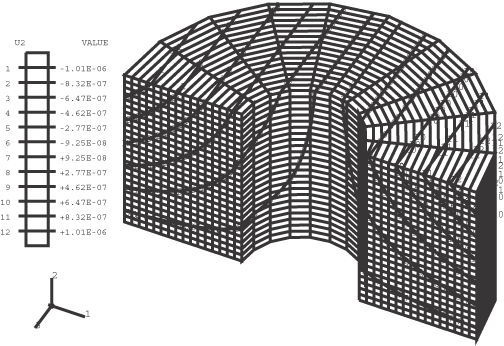
Figure 1 through Figure 4 show plots of the undeformed mesh, the deformed mesh, the contours of , and the contours of , respectively, for the CAXA4R4 model.
![]()
Input files
- ecnssfsk.inp
-
CAXA41 elements.
- ecnssfsk.f
-
User subroutine DLOAD used in ecnssfsk.inp.
- ecntsfsk.inp
-
CAXA42 elements.
- ecntsfsk.f
-
User subroutine DLOAD used in ecntsfsk.inp.
- ecnusfsk.inp
-
CAXA43 elements.
- ecnusfsk.f
-
User subroutine DLOAD used in ecnusfsk.inp.
- ecnvsfsk.inp
-
CAXA44 elements.
- ecnvsfsk.f
-
User subroutine DLOAD used in ecnvsfsk.inp.
- ecnssrsk.inp
-
CAXA4R1 elements.
- ecnssrsk.f
-
User subroutine DLOAD used in ecnssrsk.inp.
- ecntsrsk.inp
-
CAXA4R2 elements.
- ecntsrsk.f
-
User subroutine DLOAD used in ecntsrsk.inp.
- ecnusrsk.inp
-
CAXA4R3 elements.
- ecnusrsk.f
-
User subroutine DLOAD used in ecnusrsk.inp.
- ecnvsrsk.inp
-
CAXA4R4 elements.
- ecnvsrsk.f
-
User subroutine DLOAD used in ecnvsrsk.inp.
- ecnwsfsk.inp
-
CAXA81 elements.
- ecnwsfsk.f
-
User subroutine DLOAD used in ecnwsfsk.inp.
- ecnxsfsk.inp
-
CAXA82 elements.
- ecnxsfsk.f
-
User subroutine DLOAD used in ecnxsfsk.inp.
- ecnysfsk.inp
-
CAXA83 elements.
- ecnysfsk.f
-
User subroutine DLOAD used in ecnysfsk.inp.
- ecnzsfsk.inp
-
CAXA84 elements.
- ecnzsfsk.f
-
User subroutine DLOAD used in ecnzsfsk.inp.
- ecnwsrsk.inp
-
CAXA8R1 elements.
- ecnwsrsk.f
-
User subroutine DLOAD used in ecnwsrsk.inp.
- ecnxsrsk.inp
-
CAXA8R2 elements.
- ecnxsrsk.f
-
User subroutine DLOAD used in ecnxsrsk.inp.
- ecnysrsk.inp
-
CAXA8R3 elements.
- ecnysrsk.f
-
User subroutine DLOAD used in ecnysrsk.inp.
- ecnzsrsk.inp
-
CAXA8R4 elements.
- ecnzsrsk.f
-
User subroutine DLOAD used in ecnzsrsk.inp.
![]()
Figures
