Boundary conditions | ||
| ||
ProductsAbaqus/Standard
Features tested
Various types of prescribed boundary conditions are tested.
Complex boundary conditions
Elements tested
AC2D4
CPS4
Problem description
The application of real and imaginary boundary conditions is tested in the direct-solution steady-state dynamic procedure. The test is performed in a structural analysis and an acoustic analysis. Each test is performed in three steps. The first step applies nonzero real boundary conditions to particular degrees of freedom of the structure, and the steady-state harmonic response is obtained. The second step is identical to the first step except that the nonzero boundary conditions are applied to the imaginary components of the specified degrees of freedom. The expected result is that the response of the degrees of freedom for the two steps should be identical but 90° out of phase from one another. The third step is identical to the first two steps except that nonzero boundary conditions are applied to both the real and imaginary components of the specified degrees of freedom. The expected result for this step is that the response of the degrees of freedom are 45° out of phase from the response in the previous two steps.
Results and discussion
| Frequency | U11 | U21 | PU11 | PU21 | |
|---|---|---|---|---|---|
| Step 1: | 50.0 | 0.0508 | 1.110 | 180.0 | 0.0 |
| 100.0 | 0.0034 | 1.110 | 180.0 | 0.0 | |
| Step 2: | 50.0 | 0.0508 | 1.110 | −90.0 | 90.0 |
| 100.0 | 0.0034 | 1.110 | −90.0 | 90.0 | |
| Step 3: | 50.0 | 0.0719 | 1.570 | −135.0 | 45.0 |
| 100.0 | 0.0048 | 1.570 | −135.0 | 45.0 |
| Frequency | POR1 | PPOR1 | POR21 | PPOR21 | |
|---|---|---|---|---|---|
| Step 1: | 50.0 | 1.110 | 0.0 | 0.0546 | 180.0 |
| 100.0 | 1.110 | 0.0 | 0.0126 | 180.0 | |
| Step 2: | 50.0 | 1.110 | 90.0 | 0.0546 | −90.0 |
| 100.0 | 1.110 | 90.0 | 0.0126 | −90.0 | |
| Step 3: | 50.0 | 1.570 | 45.0 | 0.0772 | −135.0 |
| 100.0 | 1.570 | 45.0 | 0.0179 | −135.0 |
Input files
- xbccplxs.inp
Complex boundary conditions, structural analysis.
- xbccplxa.inp
Complex boundary conditions, acoustic analysis.
![]()
Displacement, velocity, and acceleration boundary conditions
Elements tested
B21
Problem description
The input file xbctypex.inp tests the continuity of boundary conditions in a multistep dynamic analysis. The specifications of the boundary conditions are modified between steps. The displacement, velocity, and acceleration history are varied extensively to ensure proper transitions. The fixed boundary condition is tested to ensure that proper definitions are used to set the displacements at the respective nodal positions. In addition, the specifications for the boundary conditions are varied from user-specified amplitudes to user subroutine DISP to fixed boundary condition types (i.e., encastre, etc.) and even to the removal of the boundary condition specification altogether.
Results and discussion
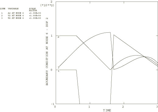
Several combinations of boundary conditions are tested on several different nodes in this test. The boundary condition specifications on degree of freedom 2 of node 6 are discussed as a typical example.
The first step defines a constant acceleration of zero as the boundary condition for degree of freedom 2 of node 6. In doing so, the default amplitude variations for dynamic analysis are employed. As described in Defining an analysis, the default choice of amplitude for a dynamic analysis is a step function except for the case of prescribed displacement and rotation boundary conditions, for which the default is a linear ramp function. Node 6 also has an initial velocity of 100. The resulting velocity and displacement should be integrated based on the prescribed acceleration variation including the initial velocity.
In the second step the specification is changed to velocity history and the step amplitude is applied linearly. Thus, the velocity should be linear from the previous value at the end of the first step to the final value (0.0) set in the definition for this step. The resulting displacement and acceleration histories should reflect this prescribed variation.
In the third step the step amplitude is applied linearly, and the boundary specification is changed to reference user subroutine DISP. In the user subroutine the acceleration is the value of the magnitude factor, which is ramped over the step. The velocity and displacements are the appropriate integrals of this variation. Since the amplitude is applied linearly, the magnitude factor is ramped during this step from the previous displacement value of 100 to the final value of 10 given in the boundary condition definition for this step. This linear definition modifies the function specified in the user subroutine such that the acceleration is linear, the velocity is quadratic, and the displacement is cubic. The curves for this typical boundary condition specification are given in Figure 1. Many other variations of boundary condition specifications are verified in the test.
Input files
- xbctypex.inp
TYPE boundary conditions.
- xbctypex.f
User subroutine DISP used in xbctypex.inp.
![]()
Velocity-type boundary conditions, static analysis
Elements tested
B21
Problem description
Input file xbcvelstat.inp tests the continuity of boundary conditions (primarily velocities) as they are modified between steps in a multistep static analysis. The velocities are always known in dynamic analysis, but they are not calculated and stored during a static analysis. Therefore, the use of velocity specifications in static analysis presents some unique problems.
Input files xbcvelres1.inp and xbcvelres2.inp test the restart capability for velocity-type boundary conditions when used in a static analysis. xbcvelres1.inp does not terminate the current step in the analysis from which the restart is made, while xbcvelres2.inp does. The input files are designed such that the results from the restart analyses are the same as those from the original analysis.
Results and discussion
The original analysis consists of four static steps using beam elements. The nine available degrees of freedom are exercised through modifications of the boundary condition specifications between steps. Boundary conditions that are specified as velocities with an amplitude reference in one step can be modified to a displacement specification with a ramped amplitude specification in the next or can be fixed or removed altogether. The continuity of the boundary conditions, when examined, is seen to be correct. The restart analyses produce results that are identical to those in the original analysis.
Input files
- xbcvelstat.inp
TYPE=VELOCITY boundary conditions, static analysis.
- xbcvelres1.inp
RESTART without END STEP test for xbcvelstat.inp.
- xbcvelres2.inp
RESTART with END STEP test for xbcvelstat.inp.