VFRICTION | ||||||||
|
| |||||||
ProductsAbaqus/Explicit
Contact points
The points considered in user subroutine VFRICTION are called contact points. Each contact point is primarily associated with a slave node or a point along a slave edge; the contact point also references the corresponding master surface that it contacts. A contact point exists for each pairing of slave node and master surface. Therefore, more than one contact point may reference the same slave node but different master surfaces, such as with contact at a corner.
The number of contact points currently being passed into user subroutine VFRICTION is nBlock. The array jConSlvUid(nNodSlv,nBlock) gives the slave surface node numbers associated with the contact points. The variable nNodSlv indicates whether a single slave node (for node-to-face contact) or two slave nodes of an edge (for edge-to-edge contact) are associated with each contact point. Similarly, the array jConMstUid(nNodMst,nBlockAnal) gives the master surface node numbers associated with each contact point; the nodes can belong to a facet, an edge, or an analytical surface. The variable nNodMst indicates the number of master nodes associated with each contact point.
An Abaqus/Explicit model can be defined in terms of an assembly of part instances (see Assembly definition). In such models a node number is an internally generated node number. If the original node number and part instance name are required, call the utility routine VGETPARTINFO (see Obtaining part information).
![]()
Local coordinate system
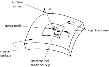
A local coordinate system is defined for each contact point to facilitate specification of frictional forces and incremental slip. The local 1-direction is tangential to the master surface; it is defined by , where is the incremental slip vector. The incremental slip vector used to define corresponds to the incremental slip in the current time increment. The master surface normal direction, , is the local 3-direction. The local 2-direction is given by , which is also tangent to the master surface. The vectors are shown in Figure 1. The direction cosines for and with respect to the global coordinate system are available in dirCosS1 and dirCosN, respectively. In the case of zero incremental slip () we choose an arbitrary direction for that is orthogonal to the normal direction, .
![]()
Frictional forces
You specify the frictional force, fTangential, at each contact point in local coordinates in this subroutine. The array fTangential is dimensioned such that only the tangential components can be specified. Any components of the frictional force that are not specified will remain equal to zero. For isotropic friction, only the first component of the frictional force need be specified since the second component should be zero. A “stick force” at each contact point is provided in the array fStickForce to assist you in setting appropriate frictional force values. The stick force is the force required to prevent additional “plastic” slipping. The stick force at each contact point is provided as a scalar value as it would act in the direction opposite to . The stick force is computed prior to calling user subroutine VFRICTION. The first component of the frictional force should be in the range between zero and the negative of the stick force value. Typically, the stick force will be positive and the first component of the applied frictional force will be negative, opposing the incremental slip. Penalty contact includes an elastic slip regime due to finite penalty stiffness; so occasionally the stick force will be negative during recovery of elastic slip, indicating that it is appropriate for the first component of the frictional force to be positive (i.e., acting in the same direction as the incremental slip). A noisy or unstable solution is likely to result if the first component of fTangential is set outside the range between zero and the negative of the stick force value.
After user subroutine VFRICTION is called, frictional forces that oppose the forces specified at the contact points are distributed to the master nodes.
![]()
User subroutine interface
       subroutine vfriction (
C Write only -
     *   fTangential,
C Read/Write -
     *   state,
C Read only -
     *   nBlock, nBlockAnal, nBlockEdge,
     *   nNodState, nNodSlv, nNodMst,
     *   nFricDir, nDir,
     *   nStates, nProps, nTemp, nFields,
     *   jFlags, rData,
     *   surfInt, surfSlv, surfMst,
     *   jConSlvUid, jConMstUid, props,
     *   dSlipFric, fStickForce, fTangPrev, fNormal,
     *   areaCont, dircosN, dircosS1,
     *   shapeSlv, shapeMst,
     *   coordSlv, coordMst,
     *   velSlv, velMst,
     *   tempSlv, tempMst,
     *   fieldSlv, fieldMst )
C
      include `vaba_param.inc'
C
      dimension fTangential(nFricDir,nBlock),
     *   state(nStates,nNodState,nBlock),
     *   jConSlvUid(nNodSlv,nBlock),
     *   jConMstUid(nNodMst,nBlockAnal),
     *   props(nProps),
     *   dSlipFric(nDir,nBlock),
     *   fStickForce(nBlock),
     *   fTangPrev(nDir,nBlock),
     *   fNormal(nBlock),
     *   areaCont(nBlock),
     *   dircosN(nDir,nBlock),
     *   dircosS1(nDir,nBlock),
     *   shapeSlv(nNodSlv,nBlockEdge),
     *   shapeMst(nNodMst,nBlockAnal),
     *   coordSlv(nDir,nNodSlv,nBlock),
     *   coordMst(nDir,nNodMst,nBlockAnal),
     *   velSlv(nDir,nNodSlv,nBlock),
     *   velMst(nDir,nNodMst,nBlockAnal),
     *   tempSlv(nBlock),
     *   tempMst(nBlockAnal),
     *   fieldSlv(nFields,nBlock),
     *   fieldMst(nFields,nBlockAnal)
C
      parameter( iKStep    = 1,
     *           iKInc     = 2,
     *           iLConType = 3,
     *           nFlags    = 3 )
C
      parameter( iTimStep      = 1,
     *           iTimGlb       = 2,
     *           iDTimCur      = 3,
     *           iFrictionWork = 4,
     *           nData         = 4 )
C
      dimension jFlags(nFlags), rData(nData)
C
      character*80 surfInt, surfSlv, surfMst
C
      user coding to define fTangential
      and, optionally, state
C
      return
end![]()
Variables to be defined
- fTangential(nFricDir,nBlock)
This array must be updated to the current values of the frictional force components for all contact points in the local tangent directions. See Figure 1 for a definition of the local coordinate system. This array will be zero (no friction force) until it is set.
![]()
Variables that can be updated
- state(nStates,nNodState,nBlock)
This array contains the user-defined, solution-dependent state variables for all the nodes on the slave surface. The use of state variables is applicable for node-to-face and node-to-analytical rigid surface contact. See Frictional behavior for more information on the size of this array. This array will be passed in containing the values of these variables prior to the call to user subroutine VFRICTION.
If any of the solution-dependent state variables are being used in conjunction with the friction behavior, they must be updated in this subroutine. These state variables need to be updated with care: outside the user subroutine these state variables are single-valued per slave node, but multiple contact points may refer to the same slave node (if it contacts a master surface at more than one point). Each contact point may be passed into the user subroutine independently in a given increment, possibly on separate calls to the user subroutine; therefore, you may end up advancing the state variables for the associated node multiple times for a single increment. To keep track of whether or not a node state is advanced, you may want to use one of the state variables exclusively for this purpose. You could set that selected state variable to the current increment number and update the state only if it is not already set to the current increment number.
![]()
Variables passed in for information
- nBlock
Number of contact points to be processed in this call to VFRICTION.
- nBlockAnal
1 for analytical rigid master surface; nBlock otherwise.
- nBlockEdge
nBlock for edge-type slave surface; 1 otherwise.
- nNodState
1 for node-to-face contact and node-to-analytical rigid surface contact.
- nNodSlv
1 for node-to-face and node-to-analytical rigid surface contact; 2 for edge-to-edge contact.
- nNodMst
1 for analytical rigid master surface; 2 for edge-type master surface; 4 for facet-type master surface.
- nFricDir
Number of tangent directions at the contact points (nFricDir = nDir - 1).
- nDir
Number of coordinate directions at the contact points (equal to 3).
- nStates
Number of user-defined state variables.
- nProps
User-specified number of property values associated with this friction model.
- nTemp
1 if the temperature is defined and 0 if the temperature is not defined.
- nFields
Number of predefined field variables.
- jFlag(1)
Step number.
- jFlag(2)
Increment number.
- jFlag(3)
1 for node-to-face contact, 2 for edge-to-edge contact, and 3 for node-to-analytical rigid surface contact.
- rData(1)
Value of step time.
- rData(2)
Value of total time.
- rData(3)
Current increment in time from to .
- rData(4)
This variable contains the value of the total frictional dissipation in the entire model from the beginning of the analysis. The units are energy per unit area.
- surfInt
User-specified surface interaction name, left justified.
- surfSlv
Slave surface name, currently set to a blank.
- surfMst
Master surface name, currently set to a blank.
- jConSlvUid(nNodSlv,nBlock)
This array lists the surface node numbers of the slave surface nodes associated with each contact point.
- jConMstUid(nNodMst,nBlockAnal)
This array lists the surface node numbers of the master surface nodes that make up the facet, edge, or analytical rigid surface associated with each contact point.
- props(nProps)
User-specified vector of property values to define the frictional behavior between the contacting surfaces.
- dSlipFric(nDir,nBlock)
This array contains the incremental frictional slip during the current time increment for each contact point in the current local coordinate system. These incremental slips correspond to tangential motion in the time increment from to . This incremental slip is used to define the local coordinate system at each contact point (see Figure 1) so that only the first component of dSlipFric can be nonzero in the local system.
- fStickForce(nBlock)
This array contains the magnitude of frictional force required to enforce stick conditions at each contact point. This force depends on the previous frictional force, the value of the penalty stiffness, and the previous incremental slip. The penalty stiffness is assigned automatically. Occasionally, during recovery of elastic slip associated with the penalty method, the stick force will be assigned a negative value.
- fTangPrev(nDir,nBlock)
This array contains the values of the frictional force components calculated in the previous increment but provided in the current local coordinate system (zero for nodes that were not in contact).
- fNormal(nBlock)
This array contains the magnitude of the normal force for the contact points applied at the end of current time increment; i.e., at time .
- areaCont(nBlock)
Area associated with the contact points. The sum of the contact areas among all contact points associated with a single slave node equals the surface area associated with that slave node (equal to 1 for node-based surface nodes). Therefore, the contact area at a contact point depends on the number of contact points currently associated with the same slave node. A contact point contributes a frictional stress to the associated slave node that is equal to fTangential(1,k) divided by areaCont(k).
- dircosN(nDir,nBlock)
Direction cosines of the normals to the master surface at the contact points.
- dirCosS1(nDir,nBlock)
Direction cosines of the incremental slip at the contact points. The direction cosines are undefined (all components zero) if the incremental frictional slip is zero.
- shapeSlv(nNodSlv,nBlockEdge)
For edge-to-edge contact this array contains the shape functions of the nodes of its slave edge, evaluated at the location of the contact point. If the contact is not edge-to-edge, this array is passed in as a dummy array.
- shapeMst(nNodMst,nBlockAnal)
For node-to-face and edge-to-edge contact this array contains the shape functions of the nodes of its master surface, evaluated at the location of the contact point. If the master surface is an analytical rigid surface, this array is passed in as a dummy array.
- coordSlv(nDir,nNodSlv,nBlock)
Array containing the nDir components of the current coordinates of the contact points.
- coordMst(nDir,nNodMst,nBlockAnal)
Array containing the nDir components of the current coordinates of the master nodes associated with the contact points. If the master surface is an analytical rigid surface, this array is passed in as a dummy array.
- velSlv(nDir,nNodSlv,nBlock)
Array containing the nDir components of the current velocity of the contact points.
- velMst(nDir,nNodMst,nBlockAnal)
Array containing the nDir components of the current velocity of the master nodes associated with the contact points. If the master surface is an analytical rigid surface, this array is passed in as a dummy array.
- tempSlv(nBlock)
Current temperature of the slave surface at the contact points.
- tempMst(nBlockAnal)
Current temperature at the points on the master surface associated with the contact points.
- fieldSlv(nFields,nBlock)
Current user-specified predefined field variables on the slave surface at the contact points (initial values at the beginning of the analysis and current values during the analysis).
- fieldMst(nFields,nBlockAnal)
Current user-specified predefined field variables at the points on the master surface associated with the contact points (initial values at the beginning of the analysis and current values during the analysis).