*ORIENTATION | |||||||
|
| ||||||
ProductsAbaqus/StandardAbaqus/ExplicitAbaqus/CAE
TypeModel data
LevelPartPart instanceAssembly
Abaqus/CAEProperty module, Interaction module, and Load module
Required parameters
- NAME
-
Set this parameter equal to a label that will be used to refer to the orientation definition. Orientation names in the same input file must be unique.
![]()
Optional parameters
- DEFINITION
-
Set DEFINITION=COORDINATES (default) to define the local system by giving the coordinates of the three points a, b, and, optionally, c (the origin) appropriate to the SYSTEM choice from Figure 1. A spatially varying local coordinate system can be created for this parameter value by using a distribution to define spatially varying coordinates for points a and b. Using a distribution to define the coordinates of the optional point c is not currently supported. See Distribution definition.
Set DEFINITION=NODES to define the local system by giving global node numbers for points a, b, and, optionally, c (the origin).
Set DEFINITION=OFFSET TO NODES to define the local system by giving local node numbers (on the element where the orientation is being used) to define the points a, b, and, optionally, c (the origin) in Figure 1. This parameter value cannot be used with spring, dashpot, or JOINTC elements. In addition, it cannot be used with the KINEMATIC COUPLING, INERTIA RELIEF, or CONTACT PAIR options.
For all DEFINITION parameter values a spatially varying local coordinate system can be created for solid continuum elements and shell elements by using a distribution to define a spatially varying additional rotation angle . See Distribution definition.
- LOCAL DIRECTIONS
-
This parameter is relevant only for anisotropic materials with preferred material directions (or fiber directions), such as anisotropic hyperelastic materials or, in Abaqus/Explicit, fabric materials.
Set this parameter equal to the number of local directions that are applicable to the material model (for example, two for a fabric material). The local directions are specified with respect to the orthonormal system at the material point resulting from the current orientation definition. Up to three local directions can be specified as part of the definition of a local orientation system.
For the fabric material in Abaqus/Explicit, the two yarn directions are given with respect to the in-plane axes of the orthonormal system. If no local directions are specified as part of the orientation definition, the local material directions are assumed to match the in-plane axes of the orthonormal system in the reference configuration.
- SYSTEM
-
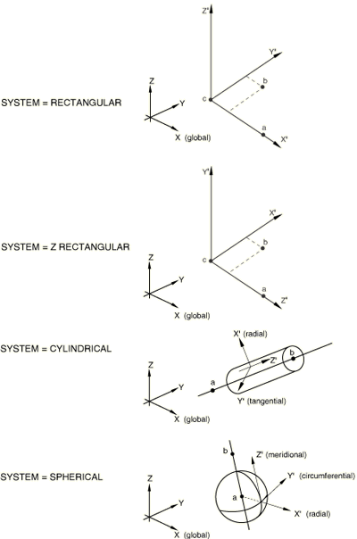
Set SYSTEM=RECTANGULAR (default) to define a rectangular Cartesian system by the three points a, b, and c shown in Figure 1. Point c is the origin of the system, point a must lie on the -axis, and point b must lie on the - plane. Although not necessary, it is intuitive to select point b such that it is on or near the local -axis.
Set SYSTEM=CYLINDRICAL to define a cylindrical system by giving the two points a and b on the polar axis of the cylindrical system (Figure 1). The local axes are 1=radial, 2=circumferential, 3=axial.
Set SYSTEM=SPHERICAL to define a spherical system by giving the center of the sphere, a, and point b on the polar axis (Figure 1). The local axes are 1=radial, 2=circumferential, 3=meridional.
Set SYSTEM=Z RECTANGULAR to define a rectangular Cartesian system by the three points a, b, and c shown in Figure 1. Point c is the origin of the system, point a must lie on the -axis, and point b must lie on the - plane. Although not necessary, it is intuitive to select point b such that it is on or near the local -axis.
Set SYSTEM=USER in an Abaqus/Standard analysis to define the local coordinate system in user subroutine ORIENT. The DEFINITION parameter and any data lines associated with the option are ignored if SYSTEM=USER.
![]()
Data lines to define an orientation using DEFINITION=COORDINATES
- First line
X-coordinate of point a.
Y-coordinate of point a.
Z-coordinate of point a.
X-coordinate of point b.
Y-coordinate of point b.
Z-coordinate of point b.
- The following items, the coordinates of point c (the origin), are optional and relevant only for SYSTEM=RECTANGULAR and SYSTEM=Z RECTANGULAR. The default location of the origin, c, is the global origin.
X-coordinate of point c.
Y-coordinate of point c.
Z-coordinate of point c.
- Second line
Local direction about which the additional rotation or rotations are given. The default is the local 1-direction. For shell, membrane, and cohesive elements this direction should have a nonzero component in the direction of the normal to the surface.
Additional rotation defined by either a single scalar value or by a distribution. An orientation defined with a distribution can be used only for solid continuum elements and shell elements. The additional rotation (in degrees) is applied to both directions orthogonal to the specified local direction. The default is zero degrees.
- Third line when the LOCAL DIRECTIONS parameter is included
X-component of the first local material direction with respect to the orthonormal system at the material point.
Y-component of the first local material direction with respect to the orthonormal system at the material point.
Z-component of the first local material direction with respect to the orthonormal system at the material point.
Repeat the above data line to define additional local directions, as needed, with each direction on a separate line.
![]()
Data lines to define a spatially varying orientation using a distribution when DEFINITION=COORDINATES
- First line
Distribution name. Data in the distribution define spatially varying coordinates for points a and b.
- Second line
Local direction about which the additional rotation or rotations are given. The default is the local 1-direction. For shell, membrane, and cohesive elements this direction should have a nonzero component in the direction of the normal to the surface.
Additional rotation defined by either a single scalar value or by a distribution. A local coordinate system defined with a distribution can be used only for solid continuum elements and shell elements. The additional rotation (in degrees) is applied to both directions orthogonal to the specified local direction. The default is zero degrees.
- Third line when the LOCAL DIRECTIONS parameter is included
X-component of the first local material direction with respect to the orthonormal system at the material point.
Y-component of the first local material direction with respect to the orthonormal system at the material point.
Z-component of the first local material direction with respect to the orthonormal system at the material point.
Repeat the above data line to define additional local directions, as needed, with each direction on a separate line.
![]()
Data lines to define an orientation using DEFINITION=NODES
- First line
Node number of the node at point a.
Node number of the node at point b.
- The next item, specification of point c (the origin), is optional and relevant only for SYSTEM=RECTANGULAR and SYSTEM=Z RECTANGULAR. The default location of the origin, c, is the global origin.
Node number of the node at point c.
- Second line
Local direction about which the additional rotation or rotations are given. The default is the local 1-direction. For shell, membrane, and cohesive elements this direction should have a nonzero component in the direction of the normal to the surface.
Additional rotation defined by either a single scalar value or by a distribution. A local coordinate system defined with a distribution can be used only for solid continuum elements and shell elements. The additional rotation (in degrees) is applied to both directions orthogonal to the specified local direction. The default is zero degrees.
- Third line when the LOCAL DIRECTIONS parameter is included
X-component of the first local material direction with respect to the orthonormal system at the material point.
Y-component of the first local material direction with respect to the orthonormal system at the material point.
Z-component of the first local material direction with respect to the orthonormal system at the material point.
Repeat the above data line to define additional local directions, as needed, with each direction on a separate line.
![]()
Data lines to define an orientation using DEFINITION=OFFSET TO NODES
- First line
Local node number of point a.
Local node number of point b.
- The next item, specification of point c (the origin), is optional and relevant only for SYSTEM=RECTANGULAR and SYSTEM=Z RECTANGULAR. The default location of the origin, c, is the first node of the element (local node number 1).
Local node number of point c.
- Second line
Local direction about which the additional rotation or rotations are given. The default is the local 1-direction. For shell, membrane, and cohesive elements this direction should have a nonzero component in the direction of the normal to the surface.
Additional rotation defined by either a single scalar value or by a distribution. A local coordinate system defined with a distribution can only be used for solid continuum elements and shell elements. The additional rotation (in degrees) is applied to both directions orthogonal to the specified local direction. The default is zero degrees.
- Third line when the LOCAL DIRECTIONS parameter is included
X-component of the first local material direction with respect to the orthonormal system at the material point.
Y-component of the first local material direction with respect to the orthonormal system at the material point.
Z-component of the first local material direction with respect to the orthonormal system at the material point.
Repeat the above data line to define additional local directions, as needed, with each direction on a separate line.
![]()
To define an orientation using a user subroutine (SYSTEM=USER)
No data lines are used with this option when SYSTEM=USER is specified. Instead, user subroutine ORIENT must be used to define the orientation.