*IMPERFECTION | ||||||||
|
| |||||||
ProductsAbaqus/StandardAbaqus/Explicit
TypeModel data
LevelModel
Optional parameters (mutually exclusive—if neither parameter is specified, Abaqus assumes that the imperfection data will be entered directly on the data lines)
- FILE
Set this parameter equal to the name of the results file from a previous Abaqus/Standard analysis containing either the mode shapes from a BUCKLE or FREQUENCY analysis or the nodal displacements from a STATIC analysis.
- INPUT
Set this parameter equal to the name of the alternate input file containing the imperfection data, in general, as the node number and imperfection values in the global coordinate system. See Input Syntax Rules for the syntax of such file names.
![]()
Required parameter if the FILE parameter is used
- STEP
Set this parameter equal to the step number (in the analysis whose results file is being used as input to this option) from which the modal or displacement data are to be read.
![]()
Optional parameters if the FILE parameter is used
- INC
Set this parameter equal to the increment number (in the analysis whose results file is being used as input to this option) from which the displacement data are to be read. If this parameter is omitted, Abaqus will read the data from the last increment available for the specified step on the results file.
- NSET
Set this parameter equal to the node set to which the geometric imperfection values are to be applied. If this parameter is omitted, the imperfection will be applied to all nodes in the model.
![]()
Optional parameter if the FILE parameter is omitted
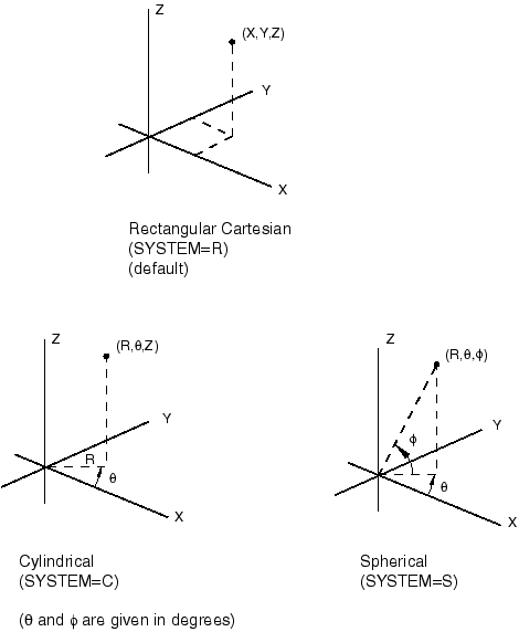
- SYSTEM
Set SYSTEM=R (default) to specify the imperfection as perturbation values of Cartesian coordinates. Set SYSTEM=C to specify the imperfection as perturbation values of cylindrical coordinates. Set SYSTEM=S to specify the imperfection as perturbation values of spherical coordinates. See Figure 1.
The SYSTEM parameter is entirely local to this option and should not be confused with the SYSTEM option. As the data lines are read, the imperfection values specified are transformed to the global rectangular Cartesian coordinate system. This transformation requires that the object be centered about the origin of the global coordinate system; i.e., the SYSTEM option should be off when specifying imperfections as perturbation values using either cylindrical or spherical coordinates.
![]()
Data lines to define the imperfection as a linear superposition of mode shapes from the results file
- First line
Mode number.
Scaling factor for this mode.
Repeat this data line as often as necessary to define the imperfection as a linear combination of mode shapes.
![]()
Data line to define the imperfection based on the solution of a static analysis from the results file
- First (and only) line
Set to 1.
Scaling factor.
![]()
Data lines to define the imperfection if the FILE and INPUT parameters are omitted
- First line
Node number.
Component of imperfection in the first coordinate direction.
Component of imperfection in the second coordinate direction.
Component of imperfection in the third coordinate direction.
Repeat this data line as often as necessary to define the imperfection.