*SYSTEM | ||||||
|
| |||||
ProductsAbaqus/StandardAbaqus/ExplicitAbaqus/CAE
TypeModel data
LevelPartPart instance
Abaqus/CAENot applicable; instancing a part in the Assembly module creates a local coordinate system.
There are no parameters associated with this option.
![]()
Data lines to define a local coordinate system
- First line
-
-
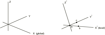
, global X-coordinate of the origin of the local coordinate system (point a in Figure 1).
-
, global Y-coordinate of the origin of the local coordinate system.
-
, global Z-coordinate of the origin of the local coordinate system.
- The following entries are not needed for a pure translation:
-
, global X-coordinate of a point on the -axis of the local coordinate system (point b in Figure 1).
-
, global Y-coordinate of a point on the -axis of the local coordinate system.
-
, global Z-coordinate of a point on the -axis of the local coordinate system.
-
- Second line (optional; if not provided, the Z-axis direction remains unchanged, and the -axis is projected onto the plane)
-
, global X-coordinate of a point in the plane of the local coordinate system, on the side of the positive -axis (for example, point c in Figure 1).
-
, global Y-coordinate of a point in the plane of the local coordinate system, on the side of the positive -axis.
-
, global Z-coordinate of a point in the plane of the local coordinate system, on the side of the positive -axis.
-