Springback of two-dimensional draw bending | ||
| ||
ProductsAbaqus/StandardAbaqus/Explicit
Problem description
The example described here is one of the benchmark tests reported at the Numisheet '93 Conference. The benchmark contains a series of six problems performed with three different materials and two different blank holder forces. One of the six problems is described here. The simulations for all the problems are described in the paper by Taylor et al. (1993).
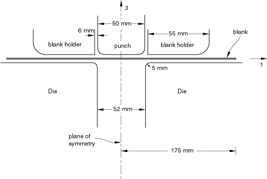
The blank initially measures 350 mm by 35 mm and is 0.78 mm thick. The problem is essentially a plane strain problem (the out-of-plane dimension for the blank is 35 mm). A cross-section of the geometry of the die, the punch, the blank holder, and the blank is shown in Figure 1. The total blank holder force is 2.45 kN, and a mass of 5 kg is attached to the blank holder. A coefficient of friction of 0.144 is used for all interacting surfaces.
The blank is made of mild steel. The material is modeled as an elastic-plastic material with isotropic elasticity, using the Hill anisotropic yield criterion for the plasticity. The following material properties are used:
| Young's modulus = 206.0 GPa |
| Poisson's ratio = 0.3 |
| Density = 7800. |
| Yield stress = 167.0 MPa |
| Anisotropic yield criterion: =1.0, =1.0402, =1.24897, =1.07895, |
| =1.0, =1.0 |
The problem is symmetric about a plane through the center of the punch, and only half of the problem is modeled. The blank is modeled with a single row of 175 first-order shell elements. Symmetry boundary conditions are applied on the plane of symmetry, and boundary conditions are applied on all the nodes of the blank to simulate the plane strain conditions. The out-of-plane dimension for the blank in the model is 5 mm; thus, the blank holder force is scaled appropriately.
The forming process is simulated in two steps with Abaqus/Explicit. The blank holder force is applied in the first step of the analysis. The force is ramped on with a smooth step definition to minimize inertia effects. In the second step of the analysis the punch is moved down 70 mm by prescribing the velocity of the rigid body reference node for the punch. The velocity is applied with a triangular smooth step amplitude function, starting and ending with zero velocity, and with a peak velocity occurring at the middle of the time period.
A significant amount of springback occurs in this case. Because the blank is very flexible and the fundamental mode of vibration is low, it would take a long simulation to obtain a quasi-static solution of the springback analysis in Abaqus/Explicit.
The springback analysis is performed with Abaqus/Standard using an import analysis. The results from the forming simulation in Abaqus/Explicit are imported into Abaqus/Standard, and a static analysis calculates the springback. During this step an artificial stress state that equilibrates the imported stress state is applied automatically by Abaqus/Standard and gradually removed during the step. The displacement obtained at the end of the step is the springback, and the stresses give the residual stress state.
Settings in the import analysis determine the reference configuration. When you choose to update the reference configuration in an import analysis, the deformed sheet with its material state at the end of the Abaqus/Explicit analysis is imported into Abaqus/Standard and the deformed configuration becomes the reference configuration. This procedure is most convenient if, during postprocessing, the displacements due to springback need to be displayed. When you do not update the reference configuration, the material state, displacements, and strains of the deformed sheet at the end of the Abaqus/Explicit analysis are imported into Abaqus/Standard, and the original configuration remains as the reference configuration. This procedure should be used if it is desirable to obtain a continuous displacement solution.
In this two-dimensional draw bending problem significant springback occurs, and large-displacement effects are included in the calculations by considering geometric nonlinearities in the step definition.
Further details of the import capability are discussed in Transferring results between Abaqus/Explicit and Abaqus/Standard.
![]()
Results and discussion
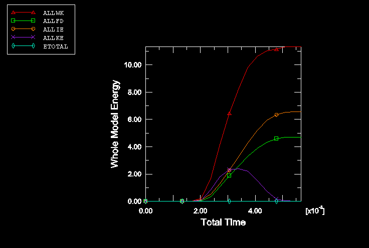
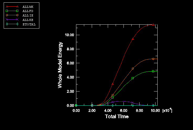
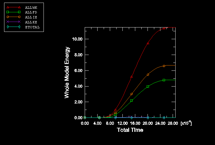
The optimum peak velocity for the punch (the value that gives quasi-static results at least cost) is determined by running the explicit analysis with peak velocities of 30 m/s, 15 m/s, and 5 m/s. The energy histories are shown in Figure 2, Figure 3, and Figure 4, respectively. From these results it is evident that the amount of kinetic energy in the model is too large at a peak velocity of 30 m/s for the analysis to simulate the quasi-static forming process, while at a peak velocity of 5 m/s the kinetic energy is virtually zero. A peak velocity for the punch of 15 m/s is chosen for the forming analysis, as the kinetic energy for this case is considered low enough not to affect the results significantly. For accurate springback analysis it is important that stresses are not influenced by inertia effects.
The blank at the end of the Abaqus/Explicit forming analysis is shown in Figure 5. The shape after springback is shown in Figure 6. The results compare well with the reported experimental data. In the numerical results the angle between the outside flange and the horizontal axis is 22° in the Abaqus/Explicit analysis and 17.1° in the Abaqus/Standard analysis. The differences in the results are due to differences in the contact calculations. In Abaqus/Explicit the change in shell thickness is accounted for during contact calculations, and the surface-to-surface contact formulation in Abaqus/Standard does the same. However, for the node-to-surface contact formulation in Abaqus/Standard when a shell is pinched between two surfaces, it is necessary to use “softened” contact to account for the shell thickness and, consequently, an approximation is made. A modified Abaqus/Explicit analysis that uses softened contact and zero shell thickness (with a zero-thickness surface) has been set up to compare the results from Abaqus/Explicit and Abaqus/Standard directly. The predicted results match closely. The average angle measured in the experiments is 17.1°, with a range from 9° to 23° in the experimental results. The results of the springback analysis when the reference configuration is updated are nearly identical to the results when the reference configuration is not updated.
![]()
Input files
- springback_exp_form.inp
Forming analysis in Abaqus/Explicit with a punch velocity of 15 m/s using contact pairs.
- springback_exp_form_gcont.inp
Forming analysis in Abaqus/Explicit with a punch velocity of 15 m/s using general contact.
- springback_std_importyes.inp
Springback analysis in Abaqus/Standard with the IMPORT, UPDATE=YES option.
- springback_std_importno.inp
Springback analysis in Abaqus/Standard with the IMPORT, UPDATE=NO option.
- springback_std_both.inp
Input data used with Abaqus/Standard for both the forming and the springback analyses.
- springback_std_both_surf.inp
Input data used with Abaqus/Standard for both the forming and the springback analyses using the surface-to-surface contact formulation.
- springback_exp_form_soft.inp
Modified forming analysis in Abaqus/Explicit with a punch velocity of 15 m/s using softened contact and contact pairs as in springback_std_both.inp.
- springback_exp_punchv30.inp
Forming analysis in Abaqus/Explicit with a punch velocity of 30 m/s using contact pairs.
- springback_exp_punchv5.inp
Forming analysis in Abaqus/Explicit with a punch velocity of 5 m/s using contact pairs.
- springback_exp_punchv30_gcont.inp
Forming analysis in Abaqus/Explicit with a punch velocity of 30 m/s using general contact.
- springback_exp_punchv5_gcont.inp
Forming analysis in Abaqus/Explicit with a punch velocity of 5 m/s using general contact.
![]()
References
- “Numerical Simulations of Sheet Metal Forming,” Proceedings of 2nd International Conference, NUMISHEET 93, Isehara, Japan, Ed. A. Makinovchi, et al.
![]()
Figures