Elastic-plastic collapse of a thin-walled elbow under in-plane bending and internal pressure | ||
| ||
ProductsAbaqus/Standard
Elbows are used in piping systems because they ovalize more readily than straight pipes and, thus, provide flexibility in response to thermal expansion and other loadings that impose significant displacements on the system. Ovalization is the bending of the pipe wall into an oval—i.e., noncircular—configuration. The elbow is, thus, behaving as a shell rather than as a beam. Straight pipe runs do not ovalize easily, so they behave essentially as beams. Thus, even under pure bending, complex interaction occurs between an elbow and the adjacent straight pipe segments; the elbow causes some ovalization in the straight pipe runs, which in turn tend to stiffen the elbow. This interaction can create significant axial gradients of bending strain in the elbow, especially in cases where the elbow is very flexible. This example provides verification of shell and elbow element modeling of such effects, through an analysis of a test elbow for which experimental results have been reported by Sobel and Newman (1979). An analysis is also included with elements of type ELBOW31B (which includes ovalization but neglects axial gradients of strain) for the elbow itself and beam elements for the straight pipe segments. This provides a comparative solution in which the interaction between the elbow and the adjacent straight pipes is neglected. The analyses predict the response up to quite large rotations across the elbow, so as to investigate possible collapse of the pipe and, particularly, the effect of internal pressure on that collapse.
Geometry and model
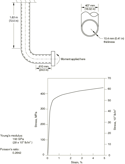
The elbow configuration used in the study is shown in Figure 1. It is a thin-walled elbow with elbow factor
and radius ratio 3.07, so the flexibility factor from Dodge and Moore (1972) is 10.3. (The flexibility factor for an elbow is the ratio of the bending flexibility of an elbow segment to that of a straight pipe of the same dimensions, for small displacements and elastic response.) This is an extremely flexible case because the pipe wall is so thin.
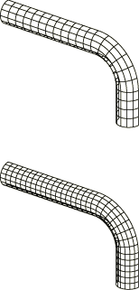
To demonstrate convergence of the overall moment-rotation behavior with respect to meshing, the two shell element meshes shown in Figure 2 are analyzed. Since the loading concerns in-plane bending only, it is assumed that the response is symmetric about the midplane of the system so that in the shell element model only one-half of the system need be modeled. Element type S8R5 is used, since tests have shown this to be the most cost-effective shell element in Abaqus (input files using element types S9R5, STRI65, and S8R for this example are included with the Abaqus release). The elbow element meshes replace each axial division in the coarser shell element model with one ELBOW32 or two ELBOW31 elements and use 4 or 6 Fourier modes to model the deformation around the pipe. Seven integration points are used through the pipe wall in all the analyses. This is usually adequate to provide accurate modeling of the progress of yielding through the section in such cases as these, where essentially monotonic straining is expected.
The ends of the system are rigidly attached to stiff plates in the experiments. These boundary conditions are easily modeled for the ELBOW elements and for the fixed end in the shell element model. For the rotating end of the shell element model the shell nodes must be constrained to a beam node that represents the motion of the end plate using a kinematic coupling constraint as described below.
The material is assumed to be isotropic and elastic-plastic, following the measured response of type 304 stainless steel at room temperature, as reported by Sobel and Newman (1979). Since all the analyses give results that are stiffer than the experimentally measured response, and the mesh convergence tests (results are discussed below) demonstrate that the meshes are convergent with respect to the overall response of the system, it seems that this stress-strain model may overestimate the material's actual strength.
![]()
Loading
The load on the pipe has two components: a “dead” load, consisting of internal pressure (with a closed end condition), and a “live” in-plane bending moment applied to the end of the system. The pressure is applied to the model in an initial step and then held constant in the second analysis step while the bending moment is increased. The pressure values range from 0.0 to 3.45 MPa (500 lb/in2), which is the range of interest for design purposes. The equivalent end force associated with the closed-end condition is applied as a follower force because it rotates with the motion of the end plane.
![]()
Kinematic boundary conditions
The fixed end of the system is assumed to be fully built-in. The loaded end is fixed into a very stiff plate. For the ELBOW element models this condition is represented by the NODEFORM boundary condition applied at this node. In the shell element model this rigid plate is represented by a single node, and the shell nodes at the end of the pipe are attached to it by using a kinematic coupling constraint and specifying that all degrees of freedom at the shell nodes are constrained to the motion of the single node.
![]()
Results and discussion
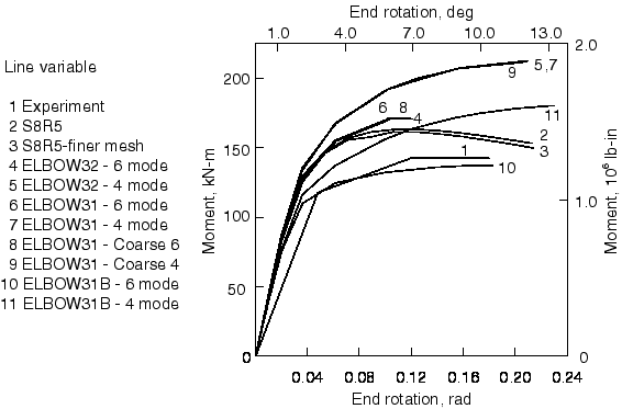
The moment-rotation responses predicted by the various analysis models and measured in the experiment, all taken at zero internal pressure, are compared in Figure 3. The figure shows that the two shell models give very similar results, overestimating the experimentally measured collapse moment by about 15%. The 6-mode ELBOW element models are somewhat stiffer than the shell models, and those with 4 Fourier modes are much too stiff. This clearly shows that, for this very flexible system, the ovalization of the elbow is too localized for even the 6-mode ELBOW representation to provide accurate results.
Since we know that the shell models are convergent with respect to discretization, the most likely explanation for the excessive stiffness in comparison to the experimentally measured response is that the material model used in the analyses is too strong. Sobel and Newman (1979) point out that the stress-strain curve measured and used in this analysis, shown in Figure 1, has a 0.2% offset yield that is 20% higher than the Nuclear Systems Materials Handbook value for type 304 stainless steel at room temperature, which suggests the possibility that the billets used for the stress-strain curve measurement may have been taken from stronger parts of the fabrication. If this is the case, it points out the likelihood that the elbow tested is rather nonuniform in strength properties in spite of the care taken in its manufacture. We are left with the conclusion that discrepancies of this magnitude cannot be eliminated in practical cases, and the design use of such analysis results must allow for them.
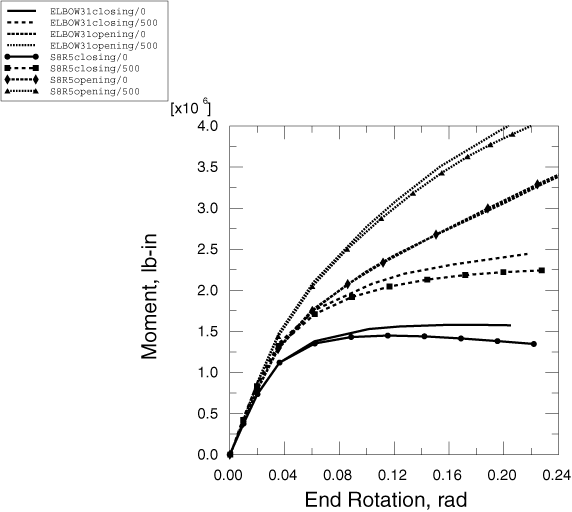
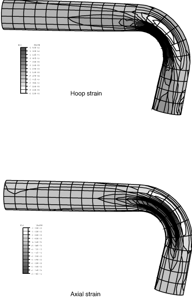
Figure 4 compares the moment-rotation response for opening and closing moments under 0 and 3.45 MPa (500 lb/in2) internal pressure and shows the strong influence of large-displacement effects. If large-displacement effects were not important, the opening and closing moments would produce the same response. However, even with a 1° relative rotation across the elbow assembly, the opening and closing moments differ by about 12%; with a 2° relative rotation, the difference is about 17%. Such magnitudes of relative rotation would not normally be considered large; in this case it is the coupling into ovalization that makes geometric nonlinearity significant. As the rotation increases, the cases with closing moment loading show collapse, while the opening moment curves do not. In both cases internal pressure shows a strong effect on the results, which is to be expected in such a thin-walled pipeline. The level of interaction between the straight pipe and the elbows is well illustrated by the strain distribution on the outside wall, shown in Figure 5. The strain contours are slightly discontinuous at the ends of the curved elbow section because the shell thickness changes at those sections.
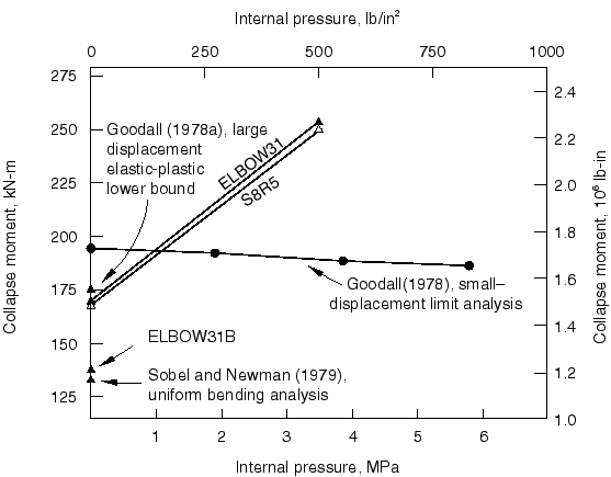
Figure 6 shows a summary of the results from this example and Uniform collapse of straight and curved pipe segments. The plot shows the collapse value of the closing moment under in-plane bending as a function of internal pressure. The strong influence of pressure on collapse is apparent. In addition, the effect of analyzing the elbow by neglecting interaction between the straight and curved segments is shown: the “uniform bending” results are obtained by using elements of type ELBOW31B in the bend and beams (element type B31) for the straight segments. The importance of the straight/elbow interaction is apparent. In this case the simpler analysis neglecting the interaction is conservative (in that it gives consistently lower values for the collapse moment), but this conservatism cannot be taken for granted. The analysis of Sobel and Newman (1979) also neglects interaction and agrees quite well with the results obtained here.
For comparison the small-displacement limit analysis results of Goodall (1978), as well as his large-displacement, elastic-plastic lower bound (Goodall, 1978a), are also shown in this figure. Again, the importance of large-displacement effects is apparent from that comparison.
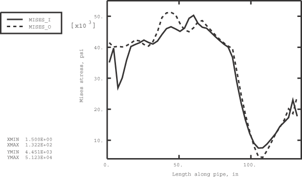
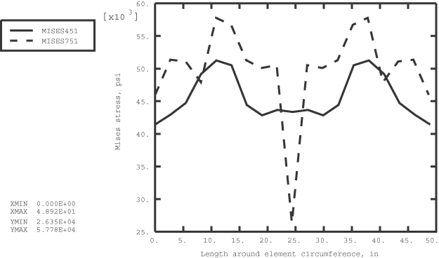
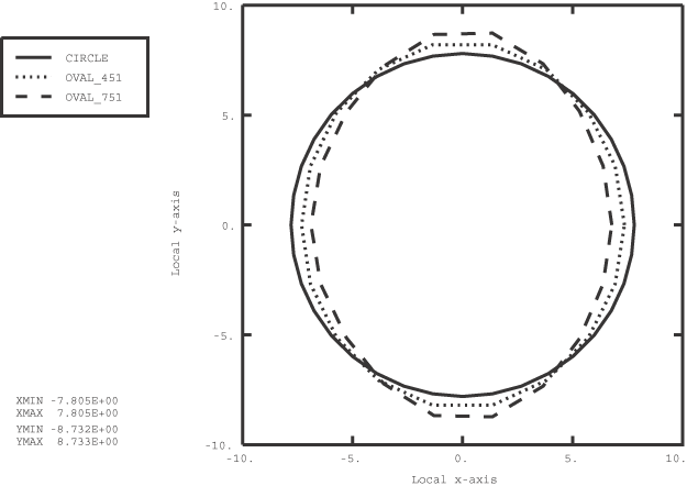
Detailed results obtained with the model that uses ELBOW31 elements are shown in Figure 7 through Figure 9. Figure 7 shows the variation of the Mises stress along the length of the piping system. The length is measured along the centerline of the pipe starting at the loaded end. The figure compares the stress distribution at the intrados (integration point 1) on the inner and outer surfaces of the elements (section points 1 and 7, respectively). Figure 8 shows the variation of the Mises stress around the circumference of two elements (451 and 751) that are located in the bend section of the model; the results are for the inner surface of the elements (section point 1). Figure 9 shows the ovalization of elements 451 and 751. A nonovalized, circular cross-section is included in the figure for comparison. From the figure it is seen that element 751, located at the center of the bend section, experiences the most severe ovalization. These three figures were produced with the aid of the elbow element postprocessing program felbow.f (Creation of a data file to facilitate the postprocessing of elbow element results: FELBOW), written in Fortran. The postprocessing programs felbow.C (A C++ version of FELBOW) and felbow.py (An Abaqus Scripting Interface version of FELBOW), written in C++ and Python, respectively, are also available for generating the data for figures such as Figure 8 and Figure 9. The user must ensure that the output variables are written to the output database to use these two programs.
![]()
Shell-to-solid submodeling
One particular case is analyzed using the shell-to-solid submodeling technique. This problem verifies the interpolation scheme in the case of double curved surfaces. A solid submodel using C3D27R elements is created around the elbow part of the pipe, spanning an angle of 40°. The finer submodel mesh has three elements through the thickness, 10 elements around half of the circumference of the cylinder, and 10 elements along the length of the elbow. Both ends are driven from the global shell model made of S8R elements. The time scale of the static submodel analysis corresponds to the arc length in the global Riks analysis. The submodel results agree closely with the shell model. The total force and the total moment in a cross-section through the submodel are written to the results (.fil) file.
![]()
Shell-to-solid coupling
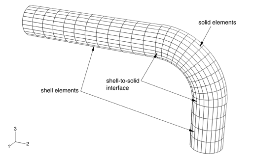
A model using the shell-to-solid coupling capability in Abaqus is included. Such a model can be used for a careful study of the stress and strain fields in the elbow. The entire elbow is meshed with C3D20R elements, and the straight pipe sections are meshed with S8R elements (see Figure 10). At each shell-to-solid interface illustrated in Figure 10, an element-based surface is defined on the edge of the solid mesh and an edge-based surface is defined on the edge of the shell mesh. A shell-to-solid coupling constraint is used in conjunction with these surfaces to couple the shell and solid meshes.
Edge-based surfaces are defined at the end of each pipe segment. These surfaces are coupled to reference nodes that are defined at the center of the pipes using a distributing coupling constraint. The loading and fixed boundary conditions are applied to the reference points. The advantage of using this method is that the pipe cross-sectional areas are free to deform; thus, ovalization at the ends is not constrained. The moment-rotation response of the shell-to-solid coupling model agrees very well with the results shown in Figure 4.
![]()
Input files
In all the following input files (with the exception of elbowcollapse_elbow31b_b31.inp, elbowcollapse_s8r5_fine.inp, and elbowcolpse_shl2sld_s8r_c3d20r.inp) the step concerning the application of the pressure load is commented out. To include the effects of the internal pressure in any given analysis, uncomment the step definition in the appropriate input file.
- elbowcollapse_elbow31b_b31.inp
ELBOW31B and B31 element model.
- elbowcollapse_elbow31_6four.inp
ELBOW31 model with 6 Fourier modes.
- elbowcollapse_elbow32_6four.inp
ELBOW32 model with 6 Fourier modes.
- elbowcollapse_s8r.inp
S8R element model.
- elbowcollapse_s8r5.inp
S8R5 element model.
- elbowcollapse_s8r5_fine.inp
Finer S8R5 element model.
- elbowcollapse_s9r5.inp
S9R5 element model.
- elbowcollapse_stri65.inp
STRI65 element model.
- elbowcollapse_submod.inp
Submodel using C3D27R elements.
- elbowcolpse_shl2sld_s8r_c3d20r.inp
Shell-to-solid coupling model using S8R and C3D20R elements.
![]()
References
- “Stress Indices and Flexibility Factors for Moment Loadings on Elbows and Curved Pipes,” Welding Research Council Bulletin, no. 179, 1972.
- “Lower Bound Limit Analysis of Curved Tubes Loaded by Combined Internal Pressure and In-Plane Bending Moment,” Research Division Report RD/B/N4360, Central Electricity Generating Board, England, 1978.
- “Large Deformations in Plastically Deforming Curved Tubes Subjected to In-Plane Bending,” Research Division Report RD/B/N4312, Central Electricity Generating Board, England, 1978a.
- “Elastic-Plastic In-Plane Bending and Buckling of an Elbow: Comparison of Experimental and Simplified Analysis Results,” Westinghouse Advanced Reactors Division, Report WARD–HT–94000–2, 1979.
![]()
Figures