Uniform collapse of straight and curved pipe segments | ||
| ||
ProductsAbaqus/Standard
The failure of pipe segments under conditions of pure bending is an interesting problem of nonlinear structural response. In the case of straight, thin-walled, metal cylinders, the failure usually occurs by the cylinder buckling into a pattern of small, diamond-shaped waves, in the same fashion as a cylinder failing under axial compression (see Buckling of a cylindrical shell under uniform axial pressure). The use of peak axial stress as a buckling criterion, taking the same critical value for any combination of axial load and bending moment, is a useful design approach—see Chapter 11 of Timoshenko and Gere (1961). However, for thicker walled cases, when the material modulus is low (such as rubber or a metal tube that shows significant yield before it collapses), it is possible to observe uniform collapse of the cylinder, in the sense that the pipe gradually ovalizes out of round and, thus, loses its bending stiffness. This one-dimensional deformation pattern in initially straight pipes was originally investigated by Brazier (1927). The collapse of initially curved pipes under bending moments is a rather different case because the response of the pipe will depend on whether the moment causes in-plane or out-of-plane response. In this example we look at in-plane loading only. For both cases the mode of deformation being studied is uniform collapse of the section—that is, it is assumed that all cross-sections deform in the same way. Since shell theory is used, this effectively reduces the problems to one dimension, thus making them attractive introductory studies to the investigation of structural collapse. It should be emphasized that, for the actual structure, the possibility of diamond-pattern buckling remains and should be investigated (by using appropriately detailed shell models) before using the results obtained in these examples for design—see Buckling of a cylindrical shell under uniform axial pressure. Elastic-plastic collapse of a thin-walled elbow under in-plane bending and internal pressure investigates collapse of curved and straight pipe segments of the same material and dimensions, but put together into an actual 90° piping elbow with adjacent straight pipe runs, thus describing a more realistic case.
The one-dimensional cross-sectional ovalization pattern expected allows very simple modeling to be adopted. Element type ELBOW31B is a pipe with uniformly deforming cross-section (using Fourier interpolation around the pipe) and, thus, is ideal for these cases: a single element suffices. As a companion, the problems are also modeled with a single axial segment of general 8-node shell elements (type S8R5). This case is somewhat more complicated because the ends of the segment modeled must be constrained to allow ovalization but no warping. Such conditions can be implemented using surface-based kinematic and distributing coupling constraints, as demonstrated in this example problem.
Problem description
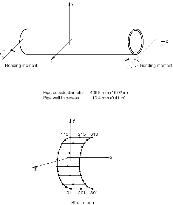
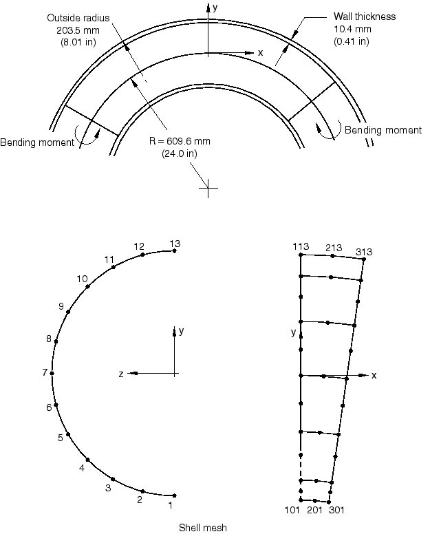
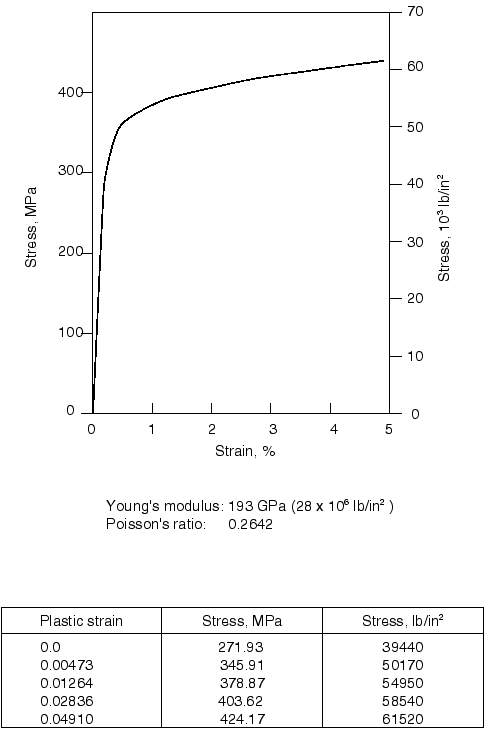
The pipes chosen for the study are relatively thin-walled, large radius pipes and are shown in Figure 1 and Figure 2. The dimensions of the pipes are taken from the more complex elbow collapse study. A unit length of pipe is considered. The material is the same and is the measured response of type 304 stainless steel specimens at room temperature, as reported by Sobel and Newman (1979). The stress-strain curve is shown in Figure 3. Results are also obtained for elastic response only, which is the case discussed by Brazier for collapse of an initially straight pipe.
![]()
Loading
The load on the pipe has two components—a “dead” load, consisting of internal pressure (with a closed-end condition), and a “live” load consisting of pure bending. The pressure is applied to the model in an initial step and then held constant as the bending moment is increased. Four different pressure values are used, ranging from no pressure to 5.17 MPa (750 lb/in2). This range seems to cover all practical values; the highest pressure gives a membrane hoop stress value of about 97 MPa (14000 lb/in2). For the shell models the equivalent end force caused by the closed-end condition is applied as a follower force because it rotates with the motion of the end plane.
![]()
Models
In all of the cases involving elastic-plastic response, seven integration points are used through the pipe wall. This is usually adequate to provide accurate modeling of the progress of yielding through the section, in such cases as these, where essentially monotonic straining is expected. In problems involving significant strain reversals (such as ratcheting or low-cycle fatigue studies), nine or more points are generally recommended.
Elbow element
The elbow element model consists of one element of type ELBOW31B. One node is restrained in all six degrees of freedom; the other is free, except for the prescribed rotation. A rotation is prescribed rather than a moment, since it is anticipated that the collapse will be unstable.
For comparison two levels of Fourier interpolation are used in the element: four modes, with 12 integration points around the pipe, and six modes, with 18 integration points around the pipe.
Typical elbow element input data for this problem are shown in unifcollapspipe_str_elbelem.inp and unifcollapspipe_curv_elbelem.inp.
Shell element
The shell element model has six elements of type S8R5 around the half-pipe. Mesh convergence studies, not included in this example, have demonstrated that such a mesh gives accurate predictions of strains and displacements in this case.
![]()
Constraints and boundary conditions for the shell element model
For the shell model the main problem is to prescribe appropriate boundary conditions. The plane 0 is a plane of symmetry, and so for nodes on that plane we must have
The motion is also symmetric about any rotated cross-sectional plane. To remove the rigid body rotation mode about the z-axis, we can choose one cross-sectional plane that does not rotate. This is taken to be the plane 0. For all nodes on that plane the symmetry constraints are
At the other end of the piece of pipe being modeled we need the same conditions, but with respect to the rotated axis system, the rotation being about the z-axis only. To impose these conditions we introduce a “beam” node, labeled b, to represent the motion of the end plane. This node is defined to have global displacement components , , and rotation , as its degrees of freedom. Pure bending of the shell model is modeled by prescribing the rotation
for the “beam” node. A rotation is prescribed rather than a moment, since it is anticipated that the collapse of the pipe will be unstable.
Surface-based kinematic and distributing couplings are applied to impose the necessary symmetry constraint on the nodes at the end of the pipe section, and a surface-based distributing coupling element is used to remove the translational rigid body mode of the pipe.
A kinematic coupling can be applied to constrain the nodes on the end plane of the shell model to impose the symmetry constraint while permitting ovalization of the cross-section. These nodes have to remain coplanar with respect to the end cross-sectional plane, with the orientation of this end plane determined by the rotation of the reference node, which is referred to as the “beam” node.
Such a condition can be implemented by constraining the end plane nodes to follow the motion of the beam node in the direction normal to the end plane. Since the constraint directions in a kinematic coupling corotate with the motion of the reference node, which in this particular model would be the beam node, the plane determined by the constraint direction would rotate along with the beam node. The initial normal to the end plane would be in the x-direction, with the end plane nodes free to translate in the y- and z-directions. However, these directions would be determined subsequently by the rotated axis system, following the motion of the beam node.
The translational rigid body mode in the y-direction can be removed by constraining the average y-direction motion of the nodes on the rotating end plane. A distributing coupling is used to constrain the average motion of the end nodes to the motion of its reference node. This reference node is then constrained in the y-direction, which constrains the motion of the end nodes only in an average sense. This can be expressed as
The elements in the shell model (S8R5) use quadratic interpolation functions; hence, the weighting factors for the nodal displacements work out to 1/6 for the corner nodes and 4/6 for the midside nodes. However, since most of the corner nodes are connected to two elements, the weights used for the distributing coupling for such nodes are 2/6, considering the contribution to both the neighboring elements. Since the only purpose of the distributing coupling is to prevent rigid body motions, the choice of weight factors is not critical.
![]()
Results and discussion
The results for the two models are discussed below.
Initially straight pipe
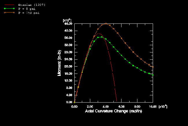
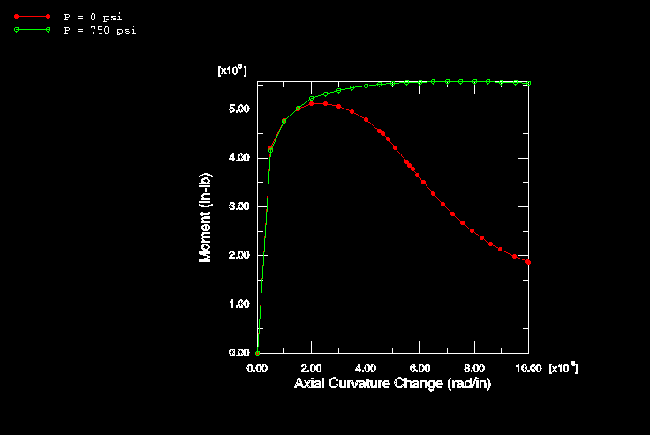
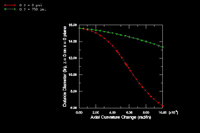
The results based on the elastic material assumption are summarized in Figure 4 and Figure 5. These plots are based on the analyses with shell elements. Figure 4 shows the variation of moment with curvature of the pipe. The unstable behavior of the collapse is evident from this plot in that the moment reaches a peak and then decreases with increasing curvature. Brazier's (1927) solution is also shown in this plot. Brazier's analysis is a first-order correction only to the usual bending theory and does not consider any pressure effect. It agrees well with the present zero pressure results up to peak load. The stiffening effect of internal pressure P is evident in this plot: the peak moment at the highest pressure (5.17 MPa, 750 lb/in2) is about 28% above the peak moment with zero pressure. The magnitude of the deformation is shown in Figure 5, where the outside dimension of the pipe section in the x–y plane is shown as a function of curvature.
The results with the elastic-plastic material behavior are rather different and are shown in Figure 6 and Figure 7. As we would expect, the moments are much lower. In addition, the severe instability in the behavior is now reduced by the internal pressure—so much so that the highest pressure solution always shows positive stiffness, even at quite large curvatures. There is also far less ovalization of the cross-section in this elastic-plastic case: the pipe is losing bending stiffness by yielding and, thus, reduces distortion of the cross-section.
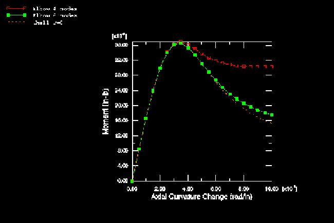
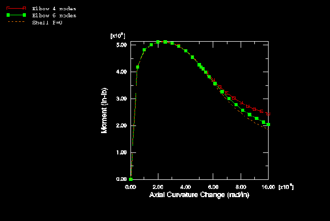
The elbow and shell element models are compared in Figure 8 (elastic, no pressure) and Figure 9 (elastic-plastic, no pressure). The elbow element models agree well with the shell element solutions, up to well beyond the collapse point, using either four or six modes, which illustrates the relative efficiency of the elbow elements for such a case.
Initially curved pipe
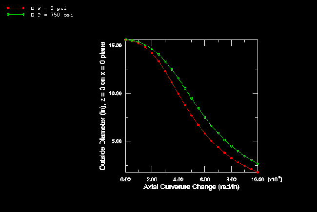
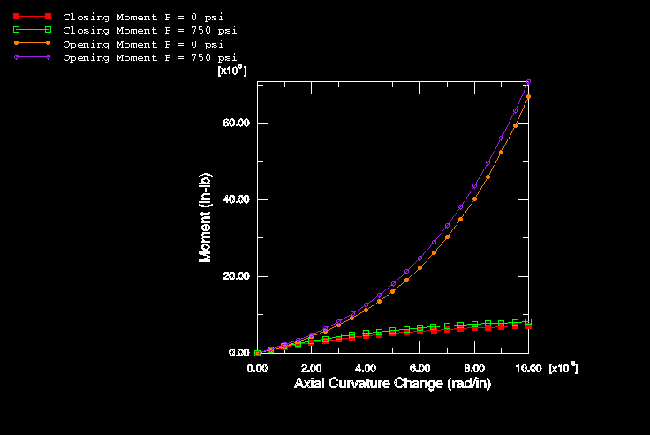
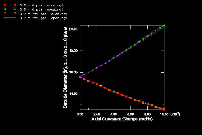
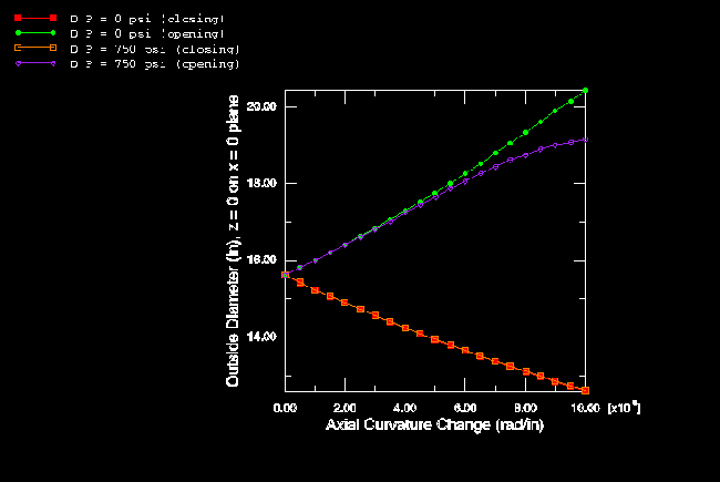
For the initially curved pipe an appropriate orientation must be used to impose the kinematic coupling correctly since the constraint directions on the end plane are not aligned initially with the global coordinate system. The results for an initially curved pipe, based on the elastic material assumption, are shown in Figure 10 and Figure 11. The response is quite different from the straight pipe results, in that opening and closing moments give distinctly different responses. With an opening moment, the ovalization of the section tends to increase the pipe's resistance to further bending, thus giving stiffening response. Under a closing moment, the pipe becomes progressively weaker in bending and never attains more than 20–25% of the moment possible in the straight pipe. The effect of internal pressure is now very much less than in the corresponding straight pipe, and the change in pipe dimensions (as shown in Figure 11) is not as severe.
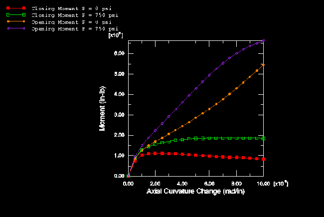
The elastic-plastic results for the same case are summarized in Figure 12 and Figure 13. In contrast to the corresponding straight pipe solutions (Figure 6 and Figure 7), the closing moment solutions show collapse (negative stiffness) at all values of internal pressure tested.
The effect of internal pressure is quite significant. The opening moment cases with lower pressures show an interesting behavior: the initial weakening of the section caused by yielding is to some extent offset later in the loading by the stiffening associated with large-displacement effects.
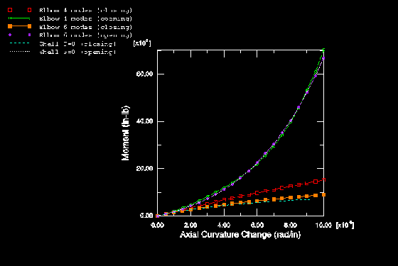
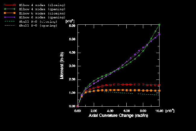
The elbow and shell element models are compared in Figure 14 (elastic, no pressure) and Figure 15 (elastic-plastic, no pressure).
![]()
Input files
- unifcollapspipe_str_elbelem.inp
Straight pipe, elastic analysis (4 Fourier mode elbow element model).
- unifcollapspipe_str_shellkcdc.inp
Straight pipe, no pressurization, elastic analysis (shell element model).
- unifcollapspipe_curv_elbelem.inp
Initially curved pipe, opening mode, elastic analysis (4 Fourier mode elbow element model).
- unifcollapspipe_curv_shellkcdc.inp
Initially curved pipe, opening mode, no pressurization, elastic analysis (shell element model).
![]()
References
- “On the Flexure of Thin Cylindrical Shells and Other 'Thin' Sections,” Proceedings of the Royal Society, London, Series A, vol. 116, pp. 104–114, 1927.
- “Plastic In-Plane Bending and Buckling of an Elbow: Comparison of Experimental and Simplified Analysis Results,” Westinghouse Advanced Reactors Division, Report WARD–HT–94000–2, 1979.
- Theory of Elastic Stability, McGraw-Hill, New York, 1961.
![]()
Figures