About cohesive elements | ||
| ||
Abaqus offers a library of cohesive elements to model the behavior of adhesive joints, interfaces in composites, and other situations where the integrity and strength of interfaces may be of interest.
Typical applications
Cohesive elements are useful in modeling adhesives, bonded interfaces, gaskets, and rock fracture. The constitutive response of these elements depends on the specific application and is based on certain assumptions about the deformation and stress states that are appropriate for each application area. The nature of the mechanical constitutive response may broadly be classified to be based on:
a continuum description of the material;
a traction-separation description of the interface; or
a uniaxial stress state appropriate for modeling gaskets and/or laterally unconstrained adhesive patches.
Each of these constitutive response types is discussed briefly below.
Continuum-based modeling
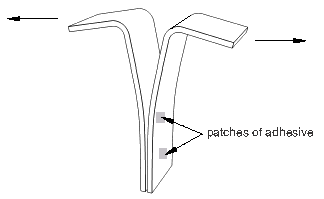
The modeling of adhesive joints involves situations where two bodies are connected together by a glue-like material (see Figure 1). A continuum-based modeling of the adhesive is appropriate when the glue has a finite thickness. The macroscopic properties, such as stiffness and strength, of the adhesive material can be measured experimentally and used directly for modeling purposes (see Defining the constitutive response of cohesive elements using a continuum approach for details). The adhesive material is generally more compliant than the surrounding material. The cohesive elements model the initial loading, the initiation of damage, and the propagation of damage leading to eventual failure in the material.
In three-dimensional problems the continuum-based constitutive model assumes one direct (through-thickness) strain, two transverse shear strains, and all (six) stress components to be active at a material point. In two-dimensional problems it assumes one direct (through-thickness) strain, one transverse shear strain, and all (four) stress components to be active at a material point.
Traction-separation-based modeling
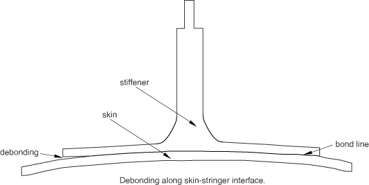
The modeling of bonded interfaces in composite materials often involves situations where the intermediate glue material is very thin and for all practical purposes may be considered to be of zero thickness (see Figure 2).
In this case the macroscopic material properties are not relevant directly, and the analyst must resort to concepts derived from fracture mechanics—such as the amount of energy required to create new surfaces (see Defining the constitutive response of cohesive elements using a traction-separation description for details). The cohesive elements model the initial loading, the initiation of damage, and the propagation of damage leading to eventual failure at the bonded interface. The behavior of the interface prior to initiation of damage is often described as linear elastic in terms of a penalty stiffness that degrades under tensile and/or shear loading but is unaffected by pure compression.
You may use the cohesive elements in areas of the model where you expect cracks to develop. However, the model need not have any crack to begin with. In fact, the precise locations (among all areas modeled with cohesive elements) where cracks initiate, as well as the evolution characteristics of such cracks, are determined as part of the solution. The cracks are restricted to propagate along the layer of cohesive elements and will not deflect into the surrounding material.
In three-dimensional problems the traction-separation-based model assumes three components of separation—one normal to the interface and two parallel to it; and the corresponding stress components are assumed to be active at a material point. In two-dimensional problems the traction-separation-based model assumes two components of separation—one normal to the interface and the other parallel to it; and the corresponding stress components are assumed to be active at a material point.
Modeling of gaskets and/or laterally unconstrained adhesive patches
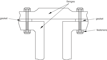
Cohesive elements also provide some limited capabilities for modeling gaskets (see Figure 3).
The constitutive response of gaskets modeled with cohesive elements can be defined using only macroscopic properties such as stiffness and strength (see Defining the constitutive response of cohesive elements using a continuum approach for details). No specialized gasket behavior (typically defined in terms of pressure versus closure) is available. Compared to the class of gasket elements available in Abaqus/Standard (About gasket elements), the cohesive elements
are fully nonlinear (can be used with finite strains and rotations);
can have mass in a dynamic analysis; and
are available in both Abaqus/Standard and Abaqus/Explicit.
It is assumed that the gaskets are subjected to a uniaxial stress state. A uniaxial stress state is also appropriate for modeling small adhesive patches that are unconstrained in the lateral direction.
Any material model in Abaqus that is available for use with a one-dimensional element (beams, trusses, or rebars)—including, for example, the hyperelastic and the elastomeric foam material models (useful in this context for modeling gaskets, sealants, or shock absorbers made out of poron)—can be used with this approach.
![]()
Spatial representation of a cohesive element
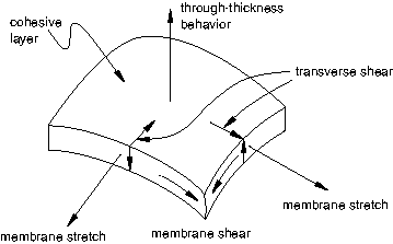
Figure 4 demonstrates the key geometrical features that are used to define cohesive elements.
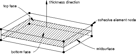
The connectivity of cohesive elements is like that of continuum elements, but it is useful to think of cohesive elements as being composed of two faces separated by a thickness. The relative motion of the bottom and top faces measured along the thickness direction (local 3-direction for three-dimensional elements; local 2-direction for two-dimensional elements—see Defining the cohesive element's initial geometry for further details on local directions) represents opening or closing of the interface. The relative change in position of the bottom and top faces measured in the plane orthogonal to the thickness direction quantifies the transverse shear behavior of the cohesive element. Stretching and shearing of the midsurface of the element (the surface halfway between the bottom and top faces) are associated with membrane strains in the cohesive element; however, it is assumed that the cohesive elements do not generate any stresses in a purely membrane response. Figure 5 shows the different deformation modes of a cohesive element.
![]()
General issues related to modeling with cohesive elements
While using cohesive elements, you should be mindful of important issues that are specific to these elements. Such issues include special considerations associated with using cohesive elements in conjunction with contact interactions, potential degradation of the stable time increment size in Abaqus/Explicit, and potential convergence problems in Abaqus/Standard. These issues are discussed in detail in Modeling with cohesive elements. Cohesive elements are typically used to bond components together. Modeling with cohesive elements also discusses methods for connecting a cohesive layer to adjacent components.
![]()
Procedures with which cohesive elements are allowed
Cohesive elements without pore pressure degrees of freedom can be used in all stress/displacement analysis types. Although they do not have any degrees of freedom other than displacement, they can be used in coupled procedures to bond together components made out of coupled temperature-displacement elements, and in Abaqus/Standard coupled pore pressure-displacement elements and/or piezoelectric elements, to simulate mechanical failure of interfaces. The response of the cohesive element in such coupled procedures is mechanical only (for example, no heat transfer occurs across the interface in a coupled temperature-displacement problem).
Cohesive elements with pore pressure degrees of freedom can be used in coupled pore fluid diffusion/stress analyses (Coupled pore fluid diffusion and stress analysis). The mechanical response of the coupled pore pressure–displacement element is the same as the equivalent displacement-only element, except that the gap fluid pressure is considered as a traction on open faces.