Creating angled construction lines | |||||||||
|
| ||||||||
Context:
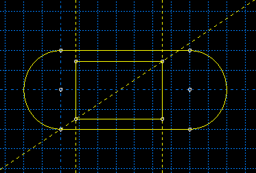
Rotating the
Sketcher
grid does not affect existing angled construction lines, but new angled
construction lines are measured from the X-axis of
the rotated grid. The following figure illustrates how an angled construction
line and a pair of vertical construction lines can be used to position the
vertices of a rectangle. (Dashed lines indicate construction geometry.)
You can also use an angled construction line to define the axis of
rotation for revolved solids and surfaces.
From the construction tools in the Sketcher toolbox, select the angled construction line tool
 . For a diagram of the tools in the Sketcher toolbox, see
The Sketcher tools.
. For a diagram of the tools in the Sketcher toolbox, see
The Sketcher tools.
Abaqus/CAE displays prompts in the prompt area to guide you through the procedure.
When you have finished creating angled construction lines, do one of the following:
-
Click mouse button 2 anywhere in the Abaqus/CAE window.
-
Select any other tool in the Sketcher toolbox.
-
Click the cancel button
 in the prompt area.
-