Construction geometry | |||||||
|
| ||||||
The
Sketcher
allows you to add construction lines and circles to your sketch; in addition,
points that you create using the isolated point tool
 are considered construction geometry. Construction lines, circles,
and points do not appear in the feature you are creating or modifying.
are considered construction geometry. Construction lines, circles,
and points do not appear in the feature you are creating or modifying.
While you are adding construction geometry and moving the cursor around the sketch, Abaqus/CAE displays preselection symbols at the following locations:
-
The intersection of the new construction geometry and sketched lines or curves.
-
The intersection of the new construction geometry and existing construction geometry.
-
The intersection of the new construction geometry and reference geometry. Abaqus/CAE displays preselection symbols only when the reference geometry was created before the feature being edited. (See Reference geometry, for more information about the behavior of reference geometry.)
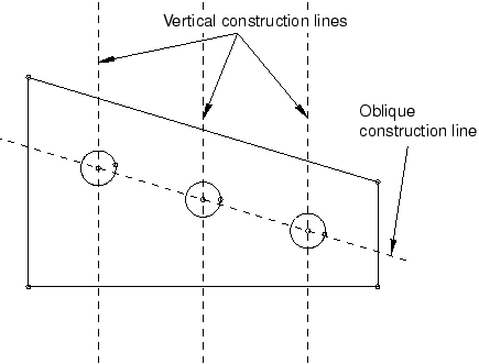
The preselection symbols generated by construction geometry allow you to align objects precisely; for example, along an oblique line or around a circle. For example, you could create an oblique construction line and several vertical construction lines to help align a group of circles, as illustrated in Figure 1.
Construction lines also define the axis of rotation when sketching revolved solids and surfaces. For more information about the relationship between construction lines and the axis of revolution, see Defining the axis of revolution for axisymmetric parts and for revolved features.
Construction geometry is shown using dashed lines to distinguish it from sketched geometry. Construction geometry is visible only while you are working on a sketch; as soon as you exit the Sketcher, the construction geometry disappears. Abaqus/CAE saves construction geometry with the original sketch; if the Sketcher is invoked to modify a sketch that included construction geometry, the construction geometry reappears along with the sketch.
To create construction geometry, select one of the construction geometry tools from the Sketcher toolbox or select from the main menu bar.
You can also convert components of your sketch into construction geometry, and you can reverse this process for items that had been converted to construction geometry. To convert a component to construction geometry, select the component and select from the main menu bar; to reverse this process, select the construction geometry component and select .