Sweeping and extruding your model | |||||
|
| ||||
Context:
Axisymmetric analytical rigid surfaces can be rotated about an axis (swept), as can the following elements: ACAXn, CAXn, CAXAn, CGAXn, DCAXn, DCCAXn, DSAXn, FAXn, MAXn, MGAXn, RAXn, SAXn, and SAXAn. Models that contain three-dimensional axisymmetric analytical rigid surfaces or CAXA elements are swept by default (the default start angle, end angle, and number of sectors vary depending on the model type). If the model contains both analytical rigid surfaces and CAXA elements, only the CAXA elements are swept by default. When you display boundary conditions for swept axisymmetric elements, symbols appear on only the original nodes and not on the swept nodes.
Cyclic symmetric models are not swept by default. When you display contours on a swept cyclic symmetric model, only nodal quantities can be contoured on the swept sectors; scalar, vector, and tensor quantities at integration points can be contoured only on the original sector.
You can extrude analytical rigid surfaces and all of the planar, two-dimensional solid elements in the Abaqus library along the Z-direction. For a list of these elements, see Two-dimensional solid element library.
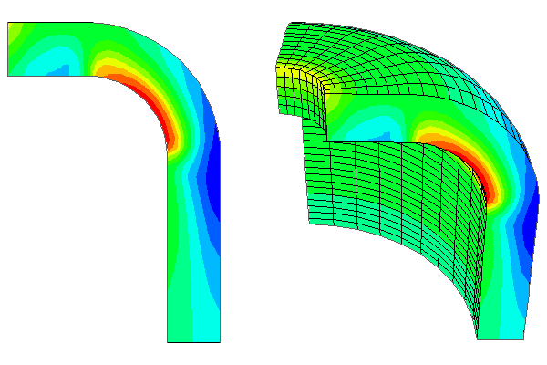
Figure 1 shows an axisymmetric planar model in a planar view (left) and the same model with an axisymmetric sweep angle of 90° and 10 sweep sectors (right).

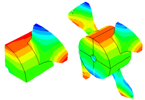
Figure 2 shows the original modeled sector of a cyclic symmetric fan (left) and sectors 1–4 of the swept model (right).

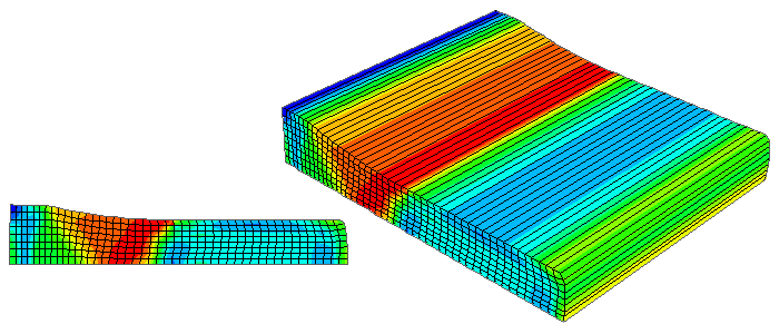
Figure 3 shows a two-dimensional planar model in a planar view (left) and the same model displayed with an extrusion depth of 0.1 (right).

Sweep elements in your axisymmetric model
![]()
Sweep analytical rigid surfaces in your axisymmetric model
![]()
Sweep your cyclic symmetric model
![]()
Extrude elements in your model
![]()