Defining mesh feature edges | |||||
|
| ||||
Context:
You use feature edges to mask the detail provided by a mesh; feature edges are typically the physical edges of the part being meshed and do not include all the additional element edges. Figure 1 shows a meshed part displayed at three different feature angles—0°, 5°, and 20°.
Figure 1. Plots showing feature angles of 0°, 5°, and 20°.
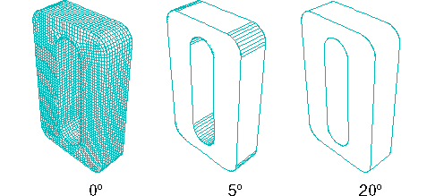
Feature edges are defined as adjacent edges with normals that differ by more than the “feature angle.” You can customize the feature angle when you select Feature mesh edge visibility. Larger angles will reduce the number of feature edges; conversely, smaller angles will cause more edges to be visible. The default mesh feature angle is 20°.