Controlling edge visibility | ||||||
|
| |||||
Context:
Using the or menu items, you can control the visibility of the following:
- Geometry edges
-
If a part or part instance is displayed with the hidden render style, Abaqus/CAE suppresses obscured geometry edges by default. Alternatively, if you toggle on the Show dotted lines in hidden render style option, Abaqus/CAE displays the obscured edges using a dotted line style.
If a part or part instance is displayed with the shaded render style, Abaqus/CAE displays the edges by default. Non-wire edges (edges attached to faces) are displayed in black. Alternatively, if you toggle off the Show edges in shaded render style option, Abaqus/CAE suppresses edge display.
If a three-dimensional part or part instance contains faces with curved edges, by default Abaqus/CAE displays gray silhouette edges originating from the faces, as shown in the hidden-line plot in Figure 1.
Figure 1. Hidden-line plot showing silhouette edges.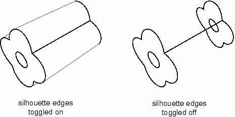
Unlike true edges, silhouette edges serve only as a visual aid; for example, you cannot select or partition a silhouette edge. Alternatively, if you toggle off the Show silhouette edges option, Abaqus/CAE displays only true edges.
Abaqus/CAE displays a curved part using a faceted representation of the part, and you use the Curve refinement option to specify the degree of faceting. For more information, see Controlling curve refinement.
- Reference representation
-
If you are creating a midsurface model and have assigned midsurface regions to cells in the solid model, the geometry of the selected cells is contained in the reference representation. By default, Abaqus/CAE displays the reference representation in the Part module. However, you can use the Show reference representation option to toggle display of the reference representation in all modules where the part or assembly is displayed. Toggle off Apply translucency to display the reference representation as opaque instead of the default translucent appearance. For more information on the reference representation, see Understanding the reference representation.
- Highlighted faces
-
You can control the style with which Abaqus/CAE displays the highlighted geometry faces of parts and assemblies. Figure 2 shows three views of a sample part with its front face selected: the left figure uses stippling as the selection method, the middle figure shows an example of isolines, and the right figure displays facet selection.
Figure 2. Highlighting faces with Stippling, Isolines, and Facets.
The stippling method offers a performance advantage, particularly for large, complex parts and assemblies. Using isolines can allow you to see a part or assembly more easily in wireframe mode than the stippling method. Finally, displaying all of a part or assembly's facets can help you debug a mesh more effectively, because meshing depends on the orientation of facets in a part or assembly.
- Mesh edges
-
For mesh edges within a meshed part or a part imported from an output database, the visibility options are:
- All edges
-
Displays all element edges. To see element edges on the interior of the model, you must also set the render style to wireframe.
- Exterior edges
-
Displays only edges on the exterior of the model.
- Feature edges
-
Displays only edges on the exterior of the model that are calculated to be feature edges. Feature edges lie between elements that have normals that differ by more than the feature angle. For more information on controlling the feature angle, see Defining mesh feature edges.
- Free edges
-
Displays only edges that belong to a single element. Free edge display is particularly useful for locating potential holes or cracks in your mesh.
These options are shown in Figure 3.
Figure 3. Model showing mesh edge display options.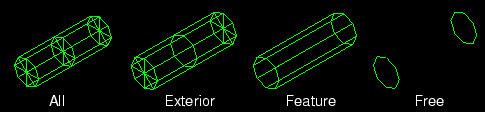
If a mesh is displayed with the shaded render style, Abaqus/CAE displays the edges by default. Alternatively, if you toggle off the Show edges in shaded render style option, Abaqus/CAE suppresses edge display.
With the exception of showing hidden geometry edges as dotted lines, you cannot control the line style, color, or thickness of edges.