Context:
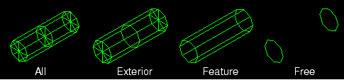
Figure 1. Model showing edge display options.
Note:
If your output database includes both homogeneous solid elements and either composite solid elements or continuum shell elements, Abaqus/CAE displays a free edge or a feature edge at the boundary between the homogeneous solid geometry and the composite geometry or continuum shell geometry.
Locate the common or superimposed Visible Edges options. The common visible edges setting always applies to the deformed shape; it applies to the undeformed shape when it is plotted individually in any plot state (undeformed, deformed, contour, symbol, or material orientation). When the undeformed shape is plotted with the deformed shape, the superimpose visible edges setting applies.
From the main menu bar, select or ; then click the Basic tab in the dialog box that appears. The Visible Edges options are on the right side of the Basic page.
To choose the element and surface edges you want to display, click one of the following:
- All edges
Displays all element and surface edges. To see element edges on the interior of the model, you must also set the render style to wireframe.
- Exterior edges
Displays only edges on the exterior of the model.
- Feature edges
Displays only edges on the exterior of the model that are calculated to be feature edges. Feature edges lie between elements that have normals that differ by more than the feature angle. The feature angle is set in the dialog box; for more information, see Defining model feature edges.
- Free edges
Displays only edges that belong to a single element. Free edge display is particularly useful for locating potential holes or cracks in your mesh.
- No edges
Suppresses the display of all edges. This choice is available only for plots in the filled or shaded render styles.
Note:
When elements are duplicated (i.e., share all the same corner nodes), Abaqus/CAE will not display the element edges in a free or feature edge plot.
Click Apply to implement your changes.
The edge visibility changes according to your specification.
Your changes are saved for the duration of the session and will affect all subsequent plots in the current viewport and in any new viewports created from the current viewport.
By default, your changes are saved for the duration of the session and will affect all subsequent plots in the current viewport and in any new viewports created from the current viewport. If you want to retain the changes you applied for subsequent sessions, save them to a file. For more information, see Saving customizations for use in subsequent sessions.