The Sketcher sheet and grid | ||||||
|
| |||||
If you are sketching the base feature of a new part, the sheet size is the same as the approximate size of the part that you provided when you created the part. The origin of the sheet is located at the origin of the part's coordinate system. Similarly, if you are creating a stand-alone sketch, the sheet size is the same as the approximate size of the sketch that you provided when you created the sketch.
If you are adding a feature to a part or to the assembly, the default sheet size depends on the size of the face on which you are sketching. The origin of the sheet is located at the centroid of the selected face. If you selected a datum plane as the sketching plane, the origin of the sheet is located at the center of the part or assembly; the sheet size depends on the total size of the part or assembly.
You can use the Sketcher customization options to increase or decrease the sheet size if it does not correspond with the size of the geometry you are trying to sketch. To access the Sketcher customization options, select the customization tool  from the Sketcher toolbox. You may need to use the magnify tool
  to view the entire Sketcher sheet within the viewport.
Abaqus/CAE overlays the sheet with a grid of invisible grid points to help you position the cursor as you draw, move, resize, or reshape objects. By default, when you move the cursor near a grid point, the cursor automatically moves, or snaps, to the point. This behavior allows you to easily position the cursor precisely on a grid point while also providing you with full control when the cursor is not close to any grid points. If it is more convenient, you can disable the snapping behavior so that you have full control over the cursor. To help you visualize the grid points underlying the Sketcher grid, Abaqus/CAE displays visible gridlines that pass through the grid points at a selected interval; for example, every other grid point.
For example, Figure 1 shows a magnified view of a sheet whose spacing is set to 2 units.
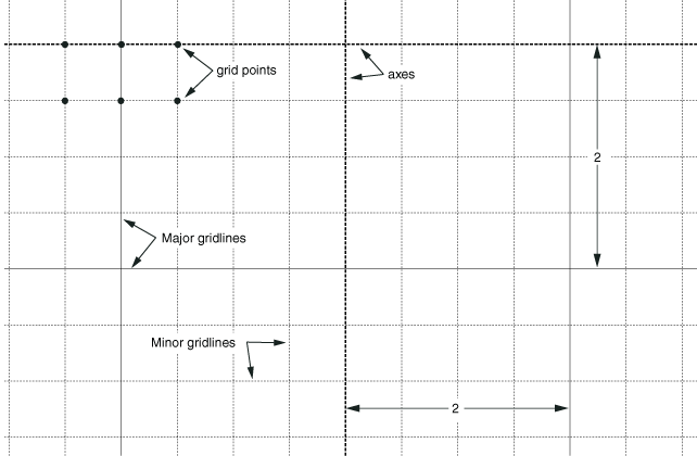
In this example the Sketcher displays both major gridlines (in a solid line style) and minor gridlines (in a thin, dashed line style). Minor gridlines appear in the Sketcher only when the magnification level is high. In addition, the thick dashed lines in the sheet indicate the X- and Y-axes of the sketch; the lines intersect at the origin of the sketch.
You can customize the appearance and behavior of the grid by choosing the spacing of grid points, the spacing of the visible gridlines that overlay the grid points, the number of minor intervals, and the sheet size. You can also realign the grid relative to the sketch by moving the origin of the grid and by rotating the grid. Your sketch can extend beyond the Sketcher grid; however, if you find that you need to sketch outside the grid, it is recommended that you increase its size to include the entire sketch. If you change the grid origin or rotation, the Sketcher displays cursor coordinates in two forms as you continue to modify the sketch. Grid coordinates indicate the cursor position using the new grid origin or rotation; sketch coordinates indicate the position based on the original grid location.
The analysis of your model can be affected by a loss of precision if the coordinates of a part are far from the origin of the part. For example, after you import a sketch to create the base feature of a part, the sketch may be relatively far from the Sketcher origin; as a result, the part will be far from its origin. To improve precision, you may have to move the part closer to its origin by moving the sketch geometry closer to the origin of the Sketcher grid using the translate tool, ![]() . You should not move the origin of the sketch closer to the geometry. Moving the origin of the Sketcher grid closer to the sketch is a graphical convenience only and has no effect on the underlying precision of the coordinates.
. You should not move the origin of the sketch closer to the geometry. Moving the origin of the Sketcher grid closer to the sketch is a graphical convenience only and has no effect on the underlying precision of the coordinates.