Using feature-based modeling effectively | ||||||
|
| |||||
- Plan a strategy
Feature-based modeling provides flexibility, but it can also add overhead to your model. For example, you can suppress an extrusion using the suppress tool in the Feature Manipulation toolset. Alternatively, you could effectively suppress the extrusion by removing it with a cut feature. Although you could restore the extrusion subsequently by removing the cut feature, the resulting part contains additional feature-based information that can slow down regeneration. Regeneration speed can be improved by using the geometry cache to save parts in different states, but the cache uses system memory that may be needed for other operations (for more information, see Tuning feature regeneration). In addition, dependencies may cause feature regeneration to fail if you add more detail to the part; and, because the extrusion is no longer visible, the cause of the failure to regenerate may be hard to determine.
Before you decide how to create a part, you should always consider if you will ever need to modify the part in the future. If you decide that you might need to modify the part, you should consider the techniques that you will use to create the features that define the part. The simplest techniques may not provide the flexibility you need for modifying the features. You may find it cumbersome to edit or suppress individual items of geometry, such as an extrusion, a fillet, or a hole.
Alternatively, if you know that you will never change the final design, you may not need the flexibility provided by feature-based modeling and can use the simplest and most convenient techniques to define the part.
In general, you should try to finish creating your parts in the Part module before you start creating part instances and positioning them in the assembly. You should try to finish creating all your parts before you apply attributes to the assembly, such as sets, loads, and boundary conditions. If you apply attributes to the assembly and then return to the Part module to modify the original part, Abaqus/CAE may not be able to determine where the attribute should be applied. For example, if you apply a pressure load to a face and then return to the Part module to partition the face into two regions, Abaqus/CAE will apply the pressure to only one of the regions.
- Use reference geometry
When you are adding a feature to a part, you should always use underlying reference geometry to define the new feature's location relative to existing features. While sketching a feature, you may be able to select reference geometry directly; for example, if you are sketching a circle, you may be able to select a vertex from the reference geometry to define its center. Alternatively, you may have to add a dimension between reference geometry and the new feature. If you do not use reference geometry to position the sketch of a new feature and you subsequently modify the part, the resulting changes to the feature can be unpredictable.
- Use dimensions
Dimensions add clarity to the sketches that define features and document your design intent for future reference. Dimensions also add constraints to your sketches. You can modify dimensions in the Sketcher, and the part and assembly will regenerate accordingly.
- Pay attention to the order in which you create features
A new feature of a part is aware of existing features. In addition, if the new feature depends on an existing feature for positioning information, Abaqus/CAE creates a parent-child relationship between the features. Parent-child relationships and the order in which you created features play an important role in feature regeneration.
A modeling scheme that is carefully ordered and follows the sequence below is less likely to run into unnecessary or ill-conditioned modeling problems:
Create the basic geometry of a part using extrusions, revolutions, cuts, and sweeps.
Add extruded, revolved, swept, and planar features.
Add round or fillet features.
Add partitions only when the rest of the geometry is complete.
- Allow for some overlap
If possible, you should allow for overlap between an existing feature and a feature that fills a hole or cuts a hole. Allowing for overlap makes your part robust, and the features are more likely to regenerate successfully. For example, when you cut a slot, extend its sketched profile above the surface you are cutting, as shown in Figure 1.
Figure 1. The sketched profile of a slot should extend beyond any surfaces that are cut.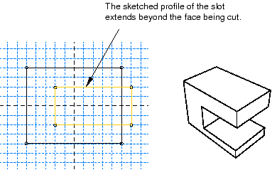
- Create solids where possible
Solid features are more robust than shell features. You may find it hard to position a group of shell features and match up the edges precisely. In contrast, sections of a solid can overlap and tolerance becomes less critical. Another advantage of using a solid is that you can use round and chamfer features to define the geometry. If you are modeling a shell, you should try to create solid features and convert the solids to shells when you have finished defining the shape. In addition, if you subsequently want to add additional shell features to a shell part, where the shell part was generated from a solid, you should do the following:
Delete the last solid-to-shell feature to convert the model back to a solid.
Add your new solid features.
Create a new solid-to-shell feature to convert the model back to a shell.