Understanding the correspondence between geometric and physical objects | |||||
|
| ||||
For example, beams and other wire parts are represented by edges in the geometric model (see Figure 1).
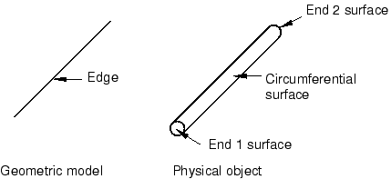
The end surfaces of these parts are represented by the vertices on either side of the edge, and the circumferential surface is represented by the line joining the vertices. To select a wire part, you can click the edge, and, if necessary, Abaqus/CAE prompts you to specify the surface of interest.
Likewise, axisymmetric shells are also represented by edges in the geometric model (see Figure 2).
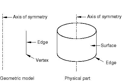
You can select the axisymmetric shell by clicking the edge in the viewport, and, if necessary, Abaqus/CAE prompts you to specify either the inside surface or the outside surface of the shell. You must select either the inside or the outside surface if you are applying a prescribed condition or contact definition to the surface. For example, if you want to apply a pressure load to a shell, you must specify which side of the shell should receive the load.
For more information on selecting surfaces, see Specifying a particular side or end of a region. For more information on modeling space, see The relationship between parts and features, and Part modeling space.