Specifying a particular side or end of a region | ||||||
|
| |||||
When you edit a surface definition, the sides are colored based on your previous selections as described below.
- Selecting sides from a shell
To distinguish the sides of a shell, Abaqus/CAE colors one side of the shell brown and the other side purple. You select a specific side by clicking either the or button in the prompt area (see Figure 1).
Figure 1. Select the side of the surface.
You also have the option of selecting , which defines a double-sided surface that includes both the brown and the purple sides of the shell. Double-sided surfaces can be used only in the following situations:
Contact interactions using three-dimensional shells, membranes, and rigid bodies in an Abaqus/Explicit analysis
Contact interactions using the small-sliding, surface-to-surface contact formulation in an Abaqus/Standard analysis
Consider the conical shell in Figure 2.
Figure 2. Colors indicate the side of a shell.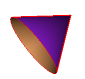
Abaqus/CAE displays the exterior side of the cone in purple and the interior side of the cone in brown. Therefore, to select the exterior of the cone, you would click in the prompt area; to select the interior, you would click .
If you select more than one shell face as part of a surface definition, you can control the color coding for each face individually. Abaqus/CAE includes a option that allows you to reverse the orientation of any individual face before creating the surface definition (see Figure 3).
Figure 3. The option becomes available for multi-faced shell surfaces.
Use this option to make all of the desired sides the same color, then select that color from the prompt area. If you select , Abaqus/CAE selects both sides of all selected faces regardless of any surfaces that you previously flipped.
In the model in Figure 4 both rounded ends are selected as part of the surface.
Figure 4. Two faces are included in the surface selection.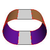
Initially, Abaqus/CAE colors the convex sides of both faces brown. However, the desired surface actually consists of one convex face and one concave face. To achieve this surface, click , and select the face on the right side of the model. Abaqus/CAE reverses the color-coding for only this face, as shown in Figure 5.
Figure 5. Flipping a surface.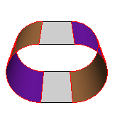
Click in the prompt area; Abaqus/CAE defines the surface on all of the brown face sides in the model.
When editing an existing surface definition, you can reselect sides by choosing either or . indicates the side that you used to create the surface previously, and indicates the other side. For example, if you selected the side to create the surface previously, that side now appears as during editing.
- Selecting sides on interior surfaces
When you select an internal face to create a surface, the surface side is ambiguous. For example, the highlighted face in Figure 6 could be either the right side of cell A or the left side of cell B.
Figure 6. Defining a surface on an internal face.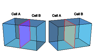
Abaqus/CAE uses the same brown/purple color-coding interface discussed above to determine which side of the surface you intended to select. Click to define a surface on the right side of cell A; click to define a surface on the left side of cell B.
- Selecting sides from a wire
If you are selecting a surface of a three-dimensional wire part instance, Abaqus/CAE displays the wire in red along with the arrowheads shown in Figure 7.
Figure 7. Arrows indicate the ends of a three-dimensional wire.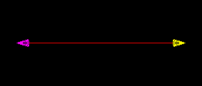
You can select the end with the magenta arrowhead, the end with the yellow arrowhead, or the circumferential surface of the part, which is indicated by the red wire (see Figure 8).
Figure 8. Select the end or the circumference of the surface.
If the wire part is two-dimensional, Abaqus/CAE distinguishes the two sides of the surface using the arrowheads shown in Figure 9.
Figure 9. Arrows indicate the top and bottom surface of a two-dimensional wire.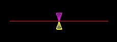
You select an arrowhead color to determine the surface side, as shown in Figure 10.
Figure 10. Select the side of the surface.
If the part is an axisymmetric shell, the inside and the outside surface of the part are indicated with arrowheads (see Figure 11). The selection options are the same as in Figure 10.
Figure 11. Arrows indicate the inside and the outside of an axisymmetric shell.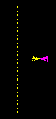
When editing an existing surface definition created on a wire, you can reselect sides by choosing either the or arrowheads. indicates the side that you used to create the surface previously, and indicates the other side. For example, if you selected the side to create the surface previously, that side now appears as during editing