What is the relationship between vertices and nodes? | ||
| ||
For example, Figure 1 shows a sketch of a two-dimensional part.
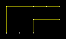
Note the locations of the nine vertices. These vertices were created by sketching several line segments along the top and bottom edges rather than one continuous line segment along each edge.
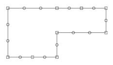
When that part or an instance of the part is seeded, square-shaped, fully constrained seeds appear at each vertex, as shown in Figure 2.
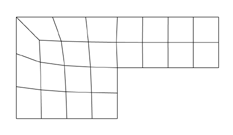
When the model is meshed, Abaqus/CAE always places nodes at the location of the fully constrained seeds that are located at vertices, as shown in Figure 3.
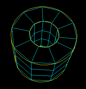
Likewise, Figure 4 shows the sketch of two concentric circles that will be extruded to form a hollow cylinder.
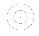
Note the location of the vertices, which the Sketcher creates at the locations you click to define the circles' perimeters.
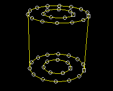
When the cylinder is seeded, square-shaped, fully constrained seeds appear at each vertex, as shown in Figure 5.
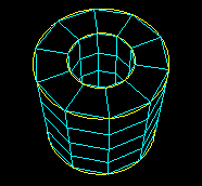
When the model is meshed, nodes always appear at the location of the fully constrained seeds that are located at vertices, as shown in Figure 6.
If you do not align the two vertices when you sketch the cylinder, you risk generating a distorted mesh. For example, the vertices of the two concentric circles are not aligned in Figure 7.
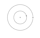
As a result, the mesh is slightly distorted on the right side, as shown in Figure 8.