What is swept meshing? | ||
| ||
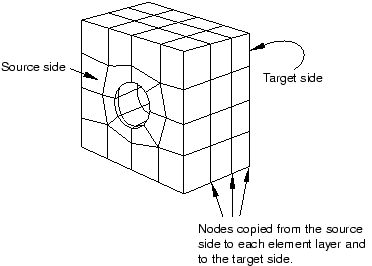
Abaqus/CAE creates a mesh on one side of the region, known as the source side.
Abaqus/CAE copies the nodes of that mesh, one element layer at a time, until the final side, known as the target side, is reached. Abaqus/CAE copies the nodes along an edge, and this edge is called the sweep path. The sweep path can be any type of edge—a straight edge, a circular edge, or a spline. If the sweep path is a straight edge or a spline, the resulting mesh is called an extruded swept mesh. If the sweep path is a circular edge, the resulting mesh is called a revolved swept mesh.
For example, Figure 1 shows an extruded swept mesh. To mesh this model, Abaqus/CAE first creates a two-dimensional mesh on the source side of the model. Next, each of the nodes in the two-dimensional mesh is copied along a straight edge to every layer until the target side is reached.
To determine if a region is swept meshable, Abaqus/CAE tests if the region can be replicated by sweeping a source side along a sweep path to a target side. In general, Abaqus/CAE selects the most complex side (for example, the side that has an isolated edge or vertex) to be the source side. In some cases you can use the mesh controls to select the sweep path. If some regions of a model are too complex to be swept meshed, Abaqus/CAE asks if you want to remove these regions from your selection before it generates a swept mesh on the remaining regions. You can use the free meshing technique to mesh the complex regions, or you can partition the regions into simplified geometry that can be structured or swept meshed.
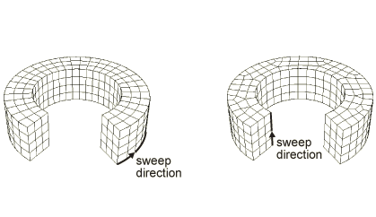
When you assign mesh controls to a region, Abaqus/CAE indicates the direction of the sweep path and allows you to control the direction. If the region can be swept in more than one direction, Abaqus/CAE may generate a very different two-dimensional mesh on the faces that it can select as the source side. As a result, the direction of the sweep path can influence the uniformity of the resulting three-dimensional swept mesh, as shown in Figure 2.
In addition, the sweep path controls the default orientation of hexahedral and wedge elements that are used to model gaskets, continuum shells, cylindrical regions using cylindrical elements, and adhesive joints using cohesive elements. For more information, see Assigning gasket elements to a region; Meshing parts with continuum shell elements; Swept meshing of cylindrical solids; and Creating a model with cohesive elements using geometry and mesh tools.