Determining which regions are meshable | ||
| ||
Structured meshing technique: green
Free meshing technique: pink
Swept meshing technique: yellow
Unmeshable: orange
Bottom-up meshing technique: light tan
See Structured meshing and mapped meshing; Free meshing; Swept meshing; and Bottom-up meshing, for information about each meshing technique. See Color coding geometry and mesh elements,” for more information about color mappings.
In many cases Abaqus/CAE can use more than one technique to mesh a region; in these cases you can either accept the default technique, or you can use the Mesh Controls dialog box to select an alternative technique. In addition, you can change the meshing techniques that are valid for a region by adding partitions to the region or by assigning a different element shape to the region. For example, if you change the element shape assignment of an unmeshable three-dimensional part instance from hexahedra to tetrahedra, the part instance becomes meshable using the free-meshing technique. For more information, see Why partition in the Mesh module?.
Note:
You must use the Mesh Controls dialog box to assign the bottom-up meshing technique to a region. To unassign the bottom-up technique, you may select another technique or click in the Mesh Controls dialog box to allow Abaqus/CAE to use the default element shape and meshing technique for the region.
The default meshing technique for two-dimensional models is the free meshing technique. If you are not satisfied with the quality of the mesh generated by the free meshing technique, or if you prefer a more regular grid-like mesh pattern, you can assign structured meshing to the simpler regions of your model. However, if your model is large and complex, identifying the simple regions where structured meshing is applicable can be a time-consuming process. To make the process faster, you can apply the structured meshing technique to the entire model, and Abaqus/CAE will do the following:
Determine if any faces are too complex to be structured meshed and ask if you wish to remove them from your selection.
Determine if any faces are poorly shaped and will result in unacceptable mesh quality and ask if you wish to remove them from your selection.
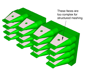
If Abaqus/CAE removed any faces from your selection, they are colored pink to indicate that they will be meshed using free meshing. Remaining faces are colored green to indicate that Abaqus/CAE will mesh them using structured meshing.
For example, Figure 1 shows a shell model of an electrical connector. The user attempted to assign structured meshing to the entire assembly, and Abaqus/CAE removed the indicated faces from their selection.
If you are meshing a solid model, you must select one or more cells and use the Mesh Controls dialog box to determine whether the structured technique can be applied to those cells. If you have a region that will be meshed using free tetrahedral meshing, you can select boundary faces and use the Mesh Controls dialog box to determine whether the structured technique can be applied to create a triangular boundary mesh prior to tetrahedral meshing of the solid.
For detailed information on controlling the mesh technique and element shape assigned to a region, see the following sections: