Choosing an element shape | |||||||
|
| ||||||
From the main menu bar, select .
Abaqus/CAE displays prompts in the prompt area to guide you through the procedure.
Tip: You can set the element shape using the  tool, located in the Mesh module toolbox.
From the list of Element Shape options, select the element shape of your choice.
If you selected a two-dimensional region, you can choose from the following element shape options:
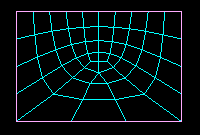
- Quad
Use exclusively quadrilateral elements. The following figure shows an example of a mesh that was constructed using this setting:
- Quad-dominated
Use primarily quadrilateral elements, but allow triangles in transition regions. This setting is the default. The following figure shows an example of a mesh that was constructed using this setting:
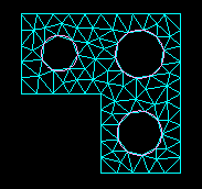
- Tri
Use exclusively triangular elements. This setting is the only one available when you apply mesh controls to faces of solid regions since the triangular face mesh will be used to generate a tetrahedral solid mesh. The following figure shows an example of a mesh that was constructed using this setting:
If you selected a three-dimensional region, you can choose from the following element shape options:
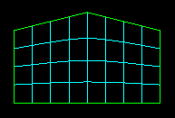
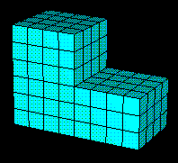
- Hex
Use exclusively hexahedral elements. This setting is the default. The following figure shows an example of a mesh that was constructed using this setting:
- Hex-dominated
Use primarily hexahedral elements, but allow some triangular prisms (wedges) in transition regions. The following figure shows an example of a mesh that was constructed using this setting:

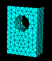
- Tet
Use exclusively tetrahedral elements. The following figure shows an example of a mesh that was constructed using this setting:
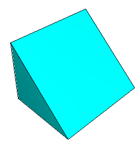
- Wedge
Use exclusively wedge elements. The following figure shows an example of a single-element mesh that was constructed using this setting: