Top-down meshing | |||||||
|
| ||||||
- Structured meshing
Structured meshing is the top-down technique that gives you the most control over your mesh because it applies preestablished mesh patterns to particular model topologies. Most unpartitioned solid models are too complex to be meshed using preestablished mesh patterns. However, you can often partition complex models into simple regions with topologies for which structured meshing patterns exist. Figure 1 shows an example of a structured mesh. For more information, see Structured meshing and mapped meshing.
Figure 1. A structured mesh.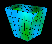
- Swept meshing
Abaqus/CAE creates swept meshes by internally generating the mesh on an edge or face and then sweeping that mesh along a sweep path. The result can be either a two-dimensional mesh created from an edge or a three-dimensional mesh created from a face. Like structured meshing, swept meshing is a top-down technique limited to models with specific topologies and geometries. Figure 2 shows an example of a swept mesh. For more information, see Swept meshing.
Figure 2. A swept mesh.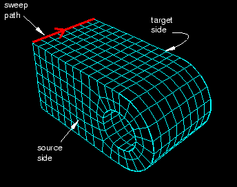
- Free meshing
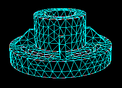
The free meshing technique is the most flexible top-down meshing technique. It uses no preestablished mesh patterns and can be applied to almost any model shape. However, free meshing provides you with the least control over the mesh since there is no way to predict the mesh pattern. Figure 3 shows an example of a free mesh. For more information, see Free meshing.
Figure 3. A free mesh generated with tetrahedral elements.